Electroguard, Prefix 80 series exit device, Electroguard™ wiring (continued) 7 – SARGENT FM8700 Surface Vertical Rod Exit Device User Manual
Page 23
The following are the input and output connector designations.
Harness Circuit
Connector
Board
Input/ Harness
Function
Pin No.*
Pin No.
Output
Wire Color
8-2
J1-1
input
Red
+24VDC power
8-1
J1-2
input
Black
-Return
8-3
J1-4
input
White
8-5
J1-5
input
Orange
External inhibit - disarm unit from
i/s or o/s (key switch, card reader, keypad)
8-6
J1-6
input
Blue
Door position sensor (Door Status/Monitor)
8-4
Chassis
Ground
Green
ESD (Earth) Ground
8-7
J1-8
output
Brown
Remote alarm relay (C.)
4-1
J1-9
output
Violet
Remote alarm relay (N.O.)
8-8
J1-10
output
Yellow
Remote alarm relay (N.C.)
4-2
J1-11
output
Grey
Latchbolt monitor relay (C.)
4-4
J1-12
output
Tan
Latchbolt monitor relay (N.O.)
4-3
J1-13
output
Pink
Latchbolt monitor relay (N.C.)
The Latchbolt monitor relay prevents the door from
being armed when latchbolt or vertical rods are
retracted.
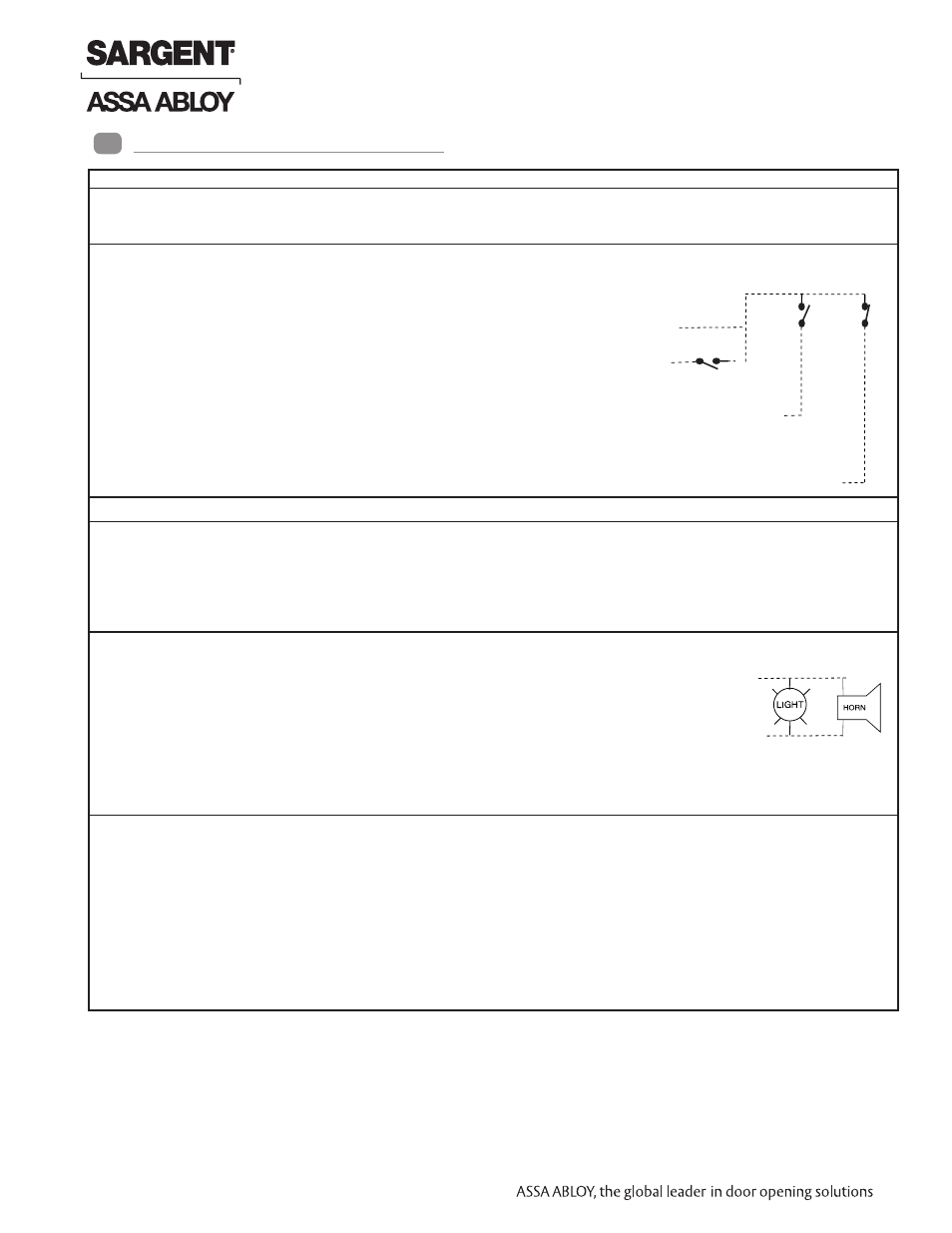
NOTES:
1. Remote alarm relay shown in power “off” state. Power “on” relay energizes; contacts reverse state.
2. Latchbolt monitor relay shown in power “off” state. Power “on” relay energizes; contacts reverse state.
flying lead
J1-16
output
Red/Black
Gang (N.C.)
flying lead
J1-15
output
Red/Yellow
Gang (N.O.)
flying lead
J1-14
output
Red/Green
Gang (C)
N.O.
N.C.
Remote Reset
N.O.
*Example: 8-2 is the 8-pin connector position #2
4-3 is the 4-pin connector position #3
Electroguard™ Wiring (Continued)
7
23 1-800-810-WIRE • www.sargentlock.com • A7690E
Copyright © 2013, Sargen
t Manufacturing Company
, an A
SS
A AB
LO
Y G
roup company
. All right
s reser
ved
.
Reproductions in whole or in par
t without express writ
ten permission of Sargen
t Manufacturing Company is prohibited
.
04/15/13
Electroguard
®
59- Prefix 80 Series Exit Device
- PR8700 Center & Top Latch Surface Vertical Rods for Pair of Doors PP8700 Center & Top Latch Surface Vertical Rods for Pair of Doors HC8700 Hurricane Code Surface Vertical Rod Exit Device NB8700 Top Latch Surface Vertical Rod 8700 Surface Vertical Rod Exit Device SP8600 Center & Top Latch Concealed Vertical Rods PR8600 Center & Top Latch Concealed Vertical Rods PP8600 Center & Top Latch Concealed Vertical Rods LR8600 Low Profile Center & Top Latch Concealed Vertical Rod Exit Devices LP8600 Low Profile Center & Top Latch Concealed Vertical Rod Exit Devices NB-WD8600 Concealed Vertical Rod Exit Device for Wood Doors WD8600 Concealed Vertical Rod Exit Device for Wood Doors NB-MD8600 Concealed Vertical Rod Exit Device for Metal Doors MD8600 Concealed Vertical Rod Exit Device for Metal Doors NB-MD8400 Series Narrow Style Concealed Vertical Rod MD8400 Series Narrow Style Concealed Vertical Rod LS8600 Low Profile Center & Top Latch Concealed Vertical Rods WS8900 Mortise Lock 8900 Mortise Lock Exit Device 8300 8888 Reversible Rim Exit Device 8800 Rim Exit Device 8500 Narrow Design Rim Exit Device HC8800 Rim Exit Device