Electroguard, Prefix 80 series exit device, 4installation instructions (continued) – SARGENT FM8700 Surface Vertical Rod Exit Device User Manual
Page 14
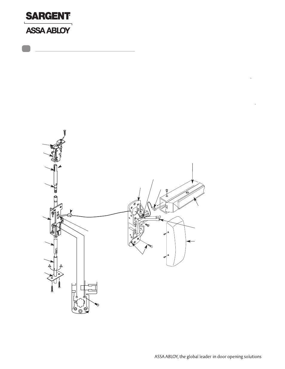
Mounting
bracket
Top
case
Top
bolt
Top
rod
Inner
chassis
Bottom
rod
Bottom
bolt
Bottom
plate
Top bolt’s flat
Wire &
connector
Wire hole
(2) #10 x 1 1/4”
Wood screw
Wire holder
Center case
chassis
*(2) 6-32 x 3/8”
Long machine screw
Center
case
chassis
Rail wire
connector
(1) #10-24
3/4”
Machine
screws
(4) #10
Wood Screws
Rail assembly
Push rail
Chassis arm
Cover
ATTACH CHASSIS
1. Feed wire and connector through chassis as shown; mount chassis
2. Snap the ElectroLynx connectors together and gather the
excess wire in the top section of the chassis. Wire tie in place.
3. Finish installation per instruction sheet A3937 and
Section 10 within this manual
D. Installing 59-WD8600/12-59-WD8600 Concealed Vertical Rod
Exit Devices
CAUTION – BEFORE STARTING:
• Check hand of door (This device is handed and not reversible)
• Door should be fitted and hung
• Verify box label for size of exit device, function and hand
PREPARE DOOR AND INSTALL RODS INTO DOOR
Refer to Instruction sheet A3937
IMPORTANT: Surface of door where
exit device is to be applied must be
flush. Clear away any raised projec-
tions to allow exit device to rest on flat
surface of door
4
Installation Instructions (Continued)
14 1-800-810-WIRE • www.sargentlock.com • A7690E
Copyright © 2013, Sargen
t Manufacturing Company
, an A
SS
A AB
LO
Y G
roup company
. All right
s reser
ved
.
Reproductions in whole or in par
t without express writ
ten permission of Sargen
t Manufacturing Company is prohibited
.
04/15/13
Electroguard
®
59- Prefix 80 Series Exit Device
- PR8700 Center & Top Latch Surface Vertical Rods for Pair of Doors PP8700 Center & Top Latch Surface Vertical Rods for Pair of Doors HC8700 Hurricane Code Surface Vertical Rod Exit Device NB8700 Top Latch Surface Vertical Rod 8700 Surface Vertical Rod Exit Device SP8600 Center & Top Latch Concealed Vertical Rods PR8600 Center & Top Latch Concealed Vertical Rods PP8600 Center & Top Latch Concealed Vertical Rods LR8600 Low Profile Center & Top Latch Concealed Vertical Rod Exit Devices LP8600 Low Profile Center & Top Latch Concealed Vertical Rod Exit Devices NB-WD8600 Concealed Vertical Rod Exit Device for Wood Doors WD8600 Concealed Vertical Rod Exit Device for Wood Doors NB-MD8600 Concealed Vertical Rod Exit Device for Metal Doors MD8600 Concealed Vertical Rod Exit Device for Metal Doors NB-MD8400 Series Narrow Style Concealed Vertical Rod MD8400 Series Narrow Style Concealed Vertical Rod LS8600 Low Profile Center & Top Latch Concealed Vertical Rods WS8900 Mortise Lock 8900 Mortise Lock Exit Device 8300 8888 Reversible Rim Exit Device 8800 Rim Exit Device 8500 Narrow Design Rim Exit Device HC8800 Rim Exit Device