Profile series v.g1.5 exit device, Rim installation instructions (continued), 5 – installation of inside escutcheon – SARGENT Profile Series v.G1.5 Exit Devices User Manual
Page 8: Outside of door inside of door
6
800-810-WIRE (9473) • www.sargentlock.com • A7856B
Profile Series v.G1.5 Exit Device
0
5
/0
4
/0
9
A
7
8
5
6
:B
C
o
p
yr
ig
h
t
©
2
0
0
9
, S
a
rg
e
n
t
M
a
n
u
fa
c
tu
ri
n
g
C
o
m
p
a
n
y,
a
n
A
S
S
A
A
B
LO
Y
G
ro
u
p
c
o
m
p
a
n
y.
A
ll
r
ig
h
ts
r
e
se
rv
e
d
.
R
e
p
ro
d
u
c
ti
o
n
in
w
h
o
le
o
r
in
p
a
rt
w
it
h
o
u
t
th
e
e
xp
re
ss
w
ri
tt
e
n
p
e
rm
is
si
o
n
o
f
S
A
R
G
EN
T
M
a
n
u
fa
c
tu
ri
n
g
is
p
ro
h
ib
it
e
d
.
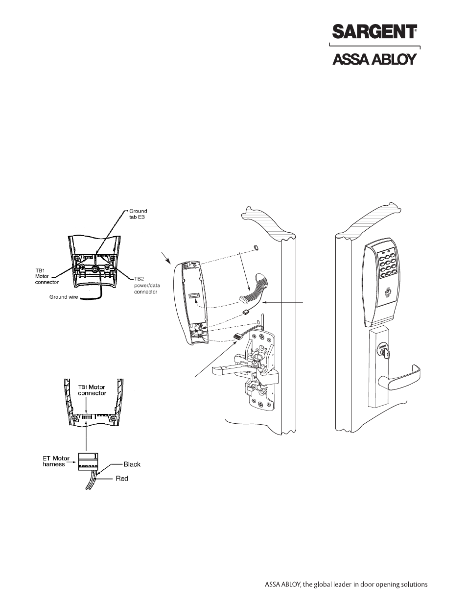
Rim Installation Instructions (Continued)
1. Connect ground wire to terminal E3 (Fig. 1), keypad harness to controller (Fig. 2), and ET motor harness to motor
connector (Fig. 3).
2. Place extra wire inside door hole and/or outside escutcheon being careful not to pinch wires.
3. Connectors go on only one way, do not offset connector and be sure they are completely seated.
Inside of
door
Outside of
door
Ground
wire
ET Motor
harness
Keypad
harness
Outside
of door
Inside
of door
6.5 – Installation of Inside Escutcheon
Fig. 1
Fig. 3
Fig. 2
Note : For RF Technology versions (G1-TU, G1-TP, G1-TA) refer to Section 10 to install through bolt screws.
Note: For RF Technology
version refer to Section 9.