Profile series v.g1.5 exit device, 3 – attaching fire stop plate, Mortise installation instructions (continued) – SARGENT Profile Series v.G1.5 Exit Devices User Manual
Page 18: 4 – installation of outside escutcheon
16
800-810-WIRE (9473) • www.sargentlock.com • A7856B
Profile Series v.G1.5 Exit Device
0
5
/0
4
/0
9
A
7
8
5
6
:B
C
o
p
yr
ig
h
t
©
2
0
0
9
, S
a
rg
e
n
t
M
a
n
u
fa
c
tu
ri
n
g
C
o
m
p
a
n
y,
a
n
A
S
S
A
A
B
LO
Y
G
ro
u
p
c
o
m
p
a
n
y.
A
ll
r
ig
h
ts
r
e
se
rv
e
d
.
R
e
p
ro
d
u
c
ti
o
n
in
w
h
o
le
o
r
in
p
a
rt
w
it
h
o
u
t
th
e
e
xp
re
ss
w
ri
tt
e
n
p
e
rm
is
si
o
n
o
f
S
A
R
G
EN
T
M
a
n
u
fa
c
tu
ri
n
g
is
p
ro
h
ib
it
e
d
.
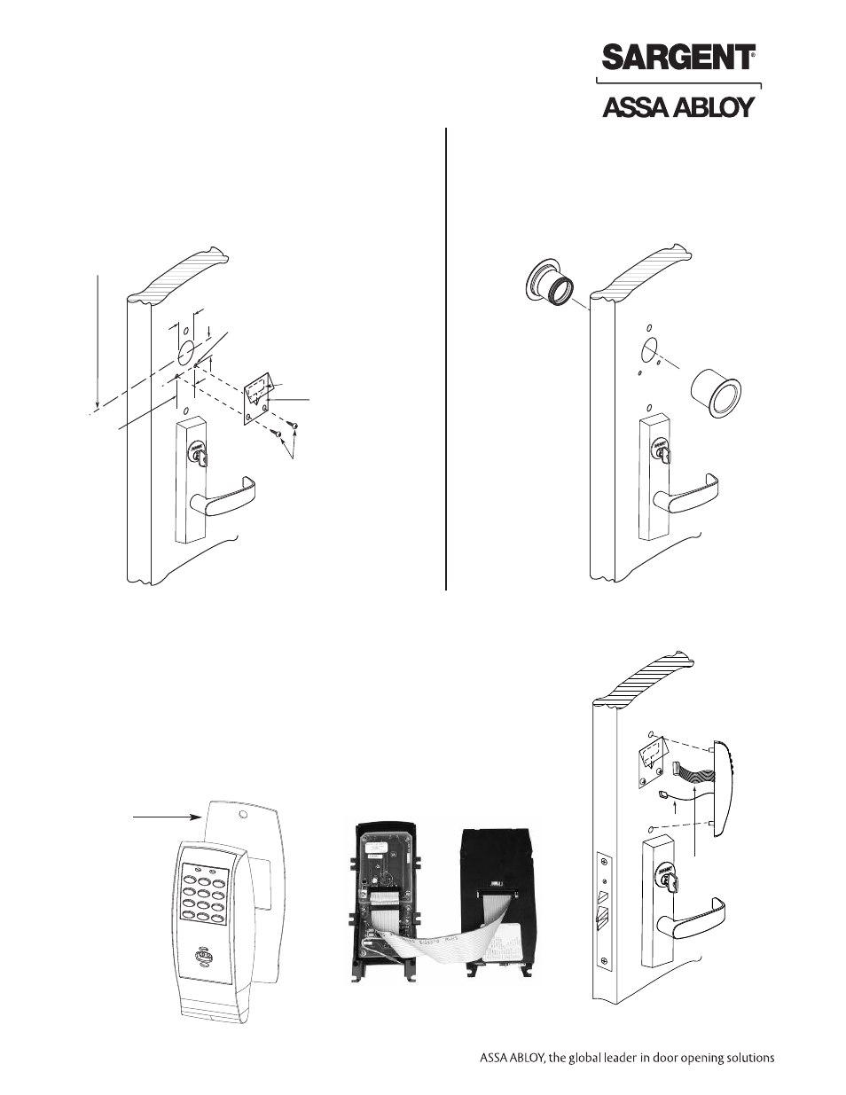
8.3 – Attaching Fire Stop Plate
C
L OF 1-1/2" Dia.
(2) Self tapping
screws #8 x 1/2"
long for wood &
metal doors
(2) 1/8" Dia.
holes required
Slot
1-1/2" Dia.
7/8"
1-1/2"
Fire stop
plate
NOTE: Fire stop plate
is required on all fire
rated doors only
NOTE: Required for 12- Fire Rated doors only.
1. Drill (2) 1/8" diameter holes if the door is not supplied
with them.
2. Secure fire stop plate to door with (2) #8 x 1/2" self
tapping screws.
Mortise Installation Instructions (Continued)
A. Insert Wires and Connector
1. For exterior applications, gasket (68-1400) should be used to seal
between escutcheon and outside door surface.
2. For 12- fire rated devices, feed keypad ribbon cable/connector from
outside of door through gasket then fire stop plate.
3. For non-12- exit devices, feed connector and wires through gasket then
hole in door.
4. Place escutcheon against door surface.
Wires & Connector
go through fire
stop plate
Ground wire
Keypad ribbon
cable/connector
8.4 – Installation of Outside Escutcheon
For exterior
applications
gasket (68-1400)
should be
placed between
the escutcheon
and the
door surface
-
+
-
+
-
+
-
+
+
-
+
-
Security
screw
Security tool
01-0297 included
Battery keeper
Battery cover
- Polarity
+ Polarity
Bottom slots
Top tab
Tabs
Top slots
Non Fire Rated Exterior Doors-
Install Weather Conduit
(P/N 52-2847) as shown below
Ribbon Cable Orientation:
Install with cable exiting DOWN, as shown.