Profile series v.g1.5 exit device, Rim installation instructions (continued), 8 – rail assembly – SARGENT Profile Series v.G1.5 Exit Devices User Manual
Page 13: 7 – inside escutcheon mounting
11
A7856B • 800-810-WIRE (9473) • www.sargentlock.com
Profile Series v.G1.5 Exit Device
0
5
/0
4
/0
9
A
7
8
5
6
:B
C
o
p
yr
ig
h
t
©
2
0
0
9
, S
a
rg
e
n
t
M
a
n
u
fa
c
tu
ri
n
g
C
o
m
p
a
n
y,
a
n
A
S
S
A
A
B
LO
Y
G
ro
u
p
c
o
m
p
a
n
y.
A
ll
r
ig
h
ts
r
e
se
rv
e
d
.
R
e
p
ro
d
u
c
ti
o
n
in
w
h
o
le
o
r
in
p
a
rt
w
it
h
o
u
t
th
e
e
xp
re
ss
w
ri
tt
e
n
p
e
rm
is
si
o
n
o
f
S
A
R
G
EN
T
M
a
n
u
fa
c
tu
ri
n
g
is
p
ro
h
ib
it
e
d
.
Rim Installation Instructions (Continued)
--
+
+
--
+
+
--
+
+
--
+
+
+
+
--
+
+
--
Security
screw
Security tool
01-0297 included
Battery keeper
Battery cover
- Polarity
+ Polarity
Bottom slots
Top tab
Tabs
Top slots
-
+
-
+
-
+
-
+
+
-
+
-
Security
screw
Security tool
01-0297 included
Battery keeper
Battery cover
- Polarity
+ Polarity
Bottom slots
Top tab
Tabs
Top slots
6.8 – Rail Assembly
Attach rail assembly according to exit installation instructions A6770
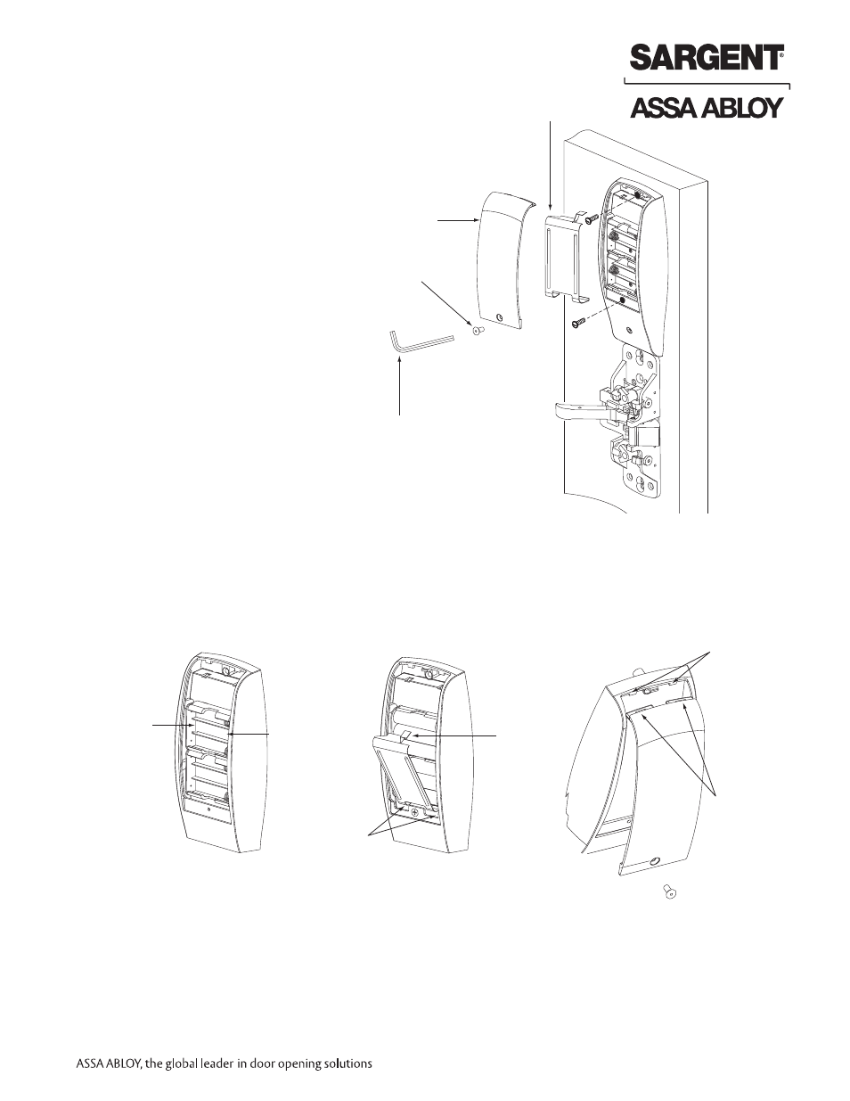
6.7 – Inside Escutcheon Mounting
1. Insert #8-32 x 1-1/4" screws
through inside escutcheon and
thread into outside escutcheon
(Fig. 1). Straighten escutcheons
and tighten securely.
NOTE: Do not install batteries if "hard-powered"
Fig. 1
Fig. 2
Fig. 3
Fig. 4
2. Place (6) “AA” batteries into
the compartment, being
careful to align polarity
properly (Fig. 2).
3. Install battery keeper clip
by inserting tabs into
bottom slots first (Fig. 3). To
remove keeper, pull on top
tab. For RF Technology
version refer to Section 9.
4. Attach battery cover to inside
escutcheon, making sure to
line up tabs with retaining
slots in battery cover. Secure
with security screw (Fig. 4).
Note: For RF
Technology versions
(G1-TU, G1-TP, G1-TA)
refer to Section 9 when
installing/removing
battery keeper.