Profile series v.g1.5 exit device, 1 – exit hardware & door prep – SARGENT Profile Series v.G1.5 Exit Devices User Manual
Page 16
14
800-810-WIRE (9473) • www.sargentlock.com • A7856B
Profile Series v.G1.5 Exit Device
0
5
/0
4
/0
9
A
7
8
5
6
:B
C
o
p
yr
ig
h
t
©
2
0
0
9
, S
a
rg
e
n
t
M
a
n
u
fa
c
tu
ri
n
g
C
o
m
p
a
n
y,
a
n
A
S
S
A
A
B
LO
Y
G
ro
u
p
c
o
m
p
a
n
y.
A
ll
r
ig
h
ts
r
e
se
rv
e
d
.
R
e
p
ro
d
u
c
ti
o
n
in
w
h
o
le
o
r
in
p
a
rt
w
it
h
o
u
t
th
e
e
xp
re
ss
w
ri
tt
e
n
p
e
rm
is
si
o
n
o
f
S
A
R
G
EN
T
M
a
n
u
fa
c
tu
ri
n
g
is
p
ro
h
ib
it
e
d
.
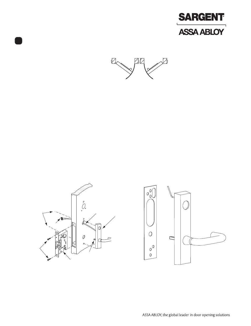
Installation Instructions for 8977-8978 Mortise Exit
Inside
Outside
Left Hand
Reverse Bevel
"LHRB"
Right Hand
Reverse Bevel
"RHRB"
IMPORTANT: BEFORE STARTING
• Check hand of door - this
device is not reversible
• Door should be fitted and hung
• Verify box label for size of exit
device, function and hand
8.1 – Exit Hardware & Door Prep
Prep door according to Exit installation instructions A6705 and appropriate templates
(metal door templates 4537 and 4538; wood door templates A7460 and A7461).
8.2 – Installation of Mortise Lock, Trim, Exit Chassis and Cylinder
A. Outside Trim
1. Slide mortise lock into door and securely fasten with (2) flat head screws
2. For exterior applications, gasket (52-0263) should be used to seal
between “ET” escutcheon and outside door surface
3. Route “ET” harness through wire cutout and out other side of door
4. Place “ET” control on door with spindle inserted through mortise lock
Outside of door
(2) Flat
head
wood
screws
ET Spindle
ET Control
Wire
harness
Mortise lock
Connector
Centerline for
(2) 1/4 - 20 x 2-3/8''
flat head
machine
screws
ET gasket
8