SARGENT Profile Series v.G1.5 Mortise Locks User Manual
Page 9
01/31/14
1-800-810-WIRE • www.sargentlock.com • A7855C 9
Copyright © 2014, Sargen
t Manufacturing Company
, an A
SS
A AB
LO
Y G
roup company
. All right
s reser
ved
.
Reproductions in whole or in par
t without express writ
ten permission of Sargen
t Manufacturing Company is prohibited
.
Profile Series v.G1.5/LK Mortise Lock
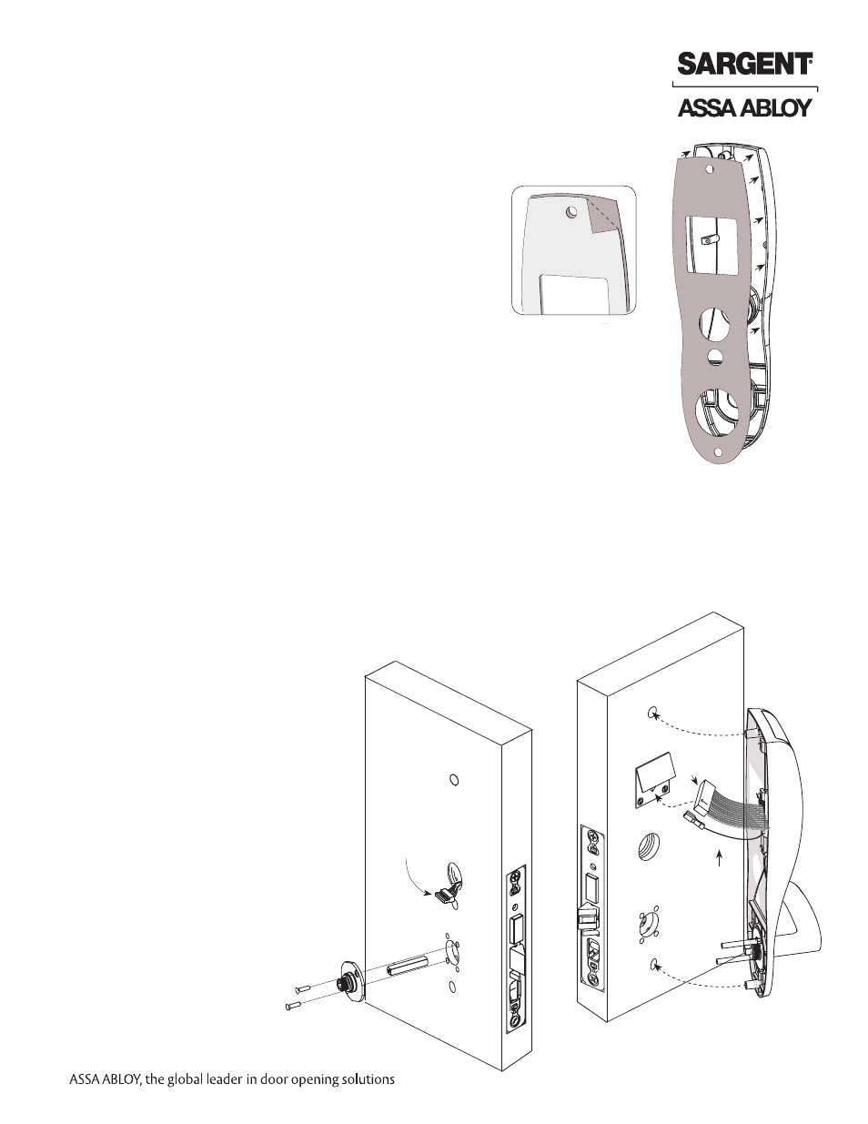
Step #6 – Install Outside Escutcheon and Lever Assembly
1A.
For 12- fire rated doors: Feed ribbon cable with connector and ground wire from
outside of door through weather seal gasket and fire stop plate (Fig. 6A).
Note: Install ribbon cable with cable exiting down
1B.
For non-12- fire rated doors: Feed ribbon cable with connector and ground
wire from outside of door through weather seal gasket (if used)
and weather conduit (not shown).
Note: Install ribbon cable with cable exiting down, orienting with side
marked ‘TOP’ facing up.
2. With outside lever horizontal, locate the outside escutcheon on the door,
while directing the mounting posts through the door and lock body (Fig. 6B).
3. Make certain the lever spindle is properly engaged in lock.
4. On the inside of the door, insert spindle into square hole of mortise lock.
5. Slide inside adapter and plate assembly over spindle
and loosely secure with 2 through
bolt screws (#8-32 x 5/8”).
Note: For 8276 and 8278,
loosely thread cylinder through
escutcheon and into the lock
body before tightening the
lock case screws and
escutcheon through-bolts.
Fig. 5B
Step #5 – Install Weatherseal Gasket (Exterior Doors)
1. Carefully remove the backing from the gasket.
2. Apply gasket to escutcheon:
• Starting in one place, press the adhesive side
of the gasket firmly against the escutcheon.
• Work around the escutcheon, pressing the sticky side
of the gasket firmly against the escutcheon edge.
• The gasket should be aligned so that all edges
of the escutcheon are covered.
3. Attach escutcheon to the door.
Note: The 43 cylinder may be used with or without a gasket.
Fig. 5A
Mortise Lock
Body Connector
and Wire
Fig. 6B
Outside of Door
Ground
Wire
Keypad
Ribbon Cable
Connector
TOP
Inside of Door
Fig. 6A