Profile series v.g1.5/lk mortise lock, Option #1 – forced / propped door (dm-), Installation – SARGENT Profile Series v.G1.5 Mortise Locks User Manual
Page 17
01/31/14
1-800-810-WIRE • www.sargentlock.com • A7855C 17
Copyright © 2014, Sargen
t Manufacturing Company
, an A
SS
A AB
LO
Y G
roup company
. All right
s reser
ved
.
Reproductions in whole or in par
t without express writ
ten permission of Sargen
t Manufacturing Company is prohibited
.
Profile Series v.G1.5/LK Mortise Lock
321
4-pin
Connector
Installation
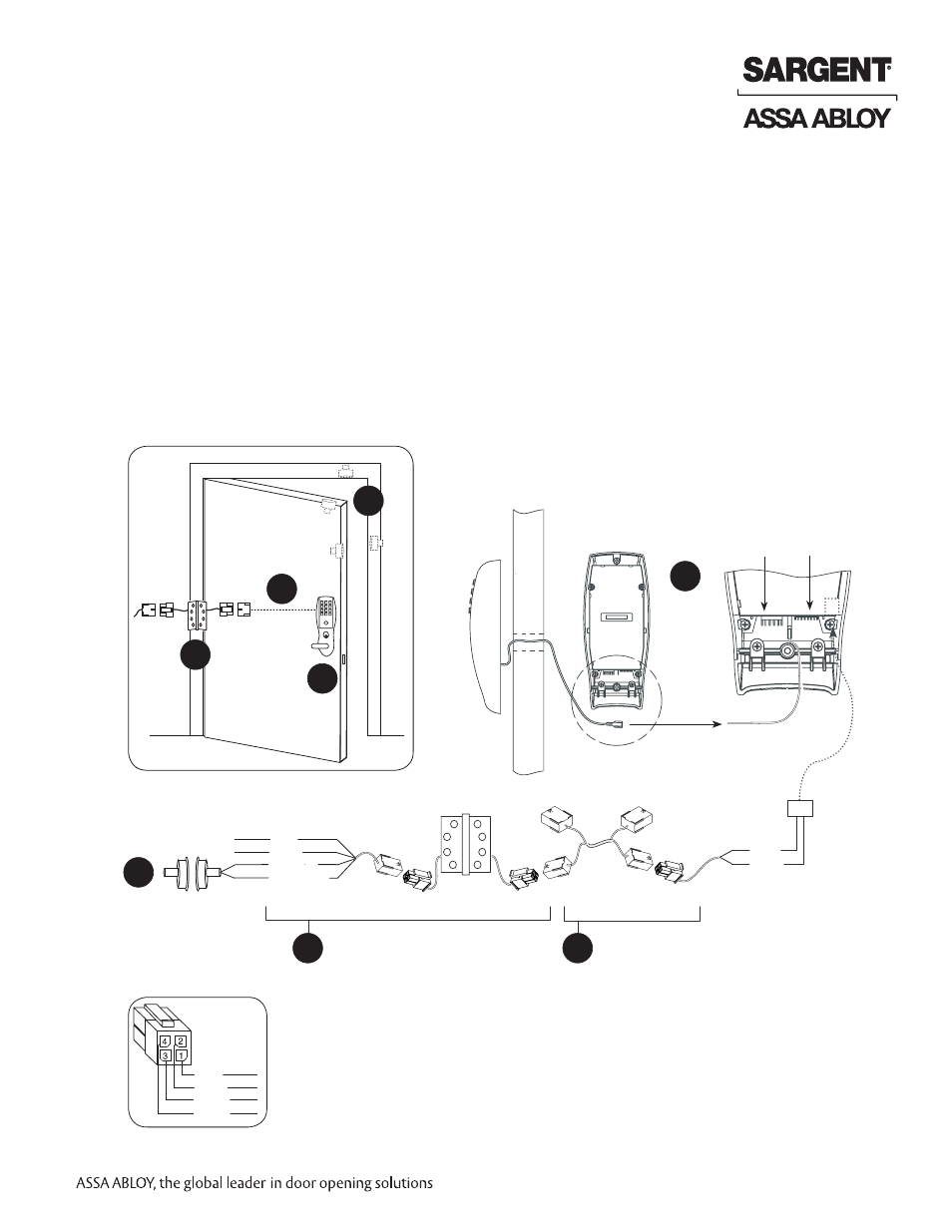
1. ElectroLynx® System Wiring Instructions (Fig. 1, 1A and Fig. 2):
a. Look for the mating part on ASSA ABLOY doors and frames.
b. Plug in all connectors during product installation (Fig. 2).
c. Hard wire door status switch as shown
2. Non-ElectroLynx® System Wiring Instructions (Fig. 1 and Fig. 2):
a. Cut the 4-pin connector off the Forced/Propped harness and hard wire to
non-ElectroLynx® two conductor door harness.
b. DM- requires two conductors.
c. Hard wire door harness to power transfer device.
d. Hard wire door status switch to power transfer device.
Fig. 2
Forced/Propped Door
Connector J4
Forced/Propped Door Option
ElectroLynx Wiring System
Door Status Switch
*Wire for switch contact closure
when door is opened - Typical
locations shown in Fig. 1
QC4A Electric Hinge
With 4-pin connectors and pigtail harness
ElectroLynx Door Harness
With 8 and 4-pin connectors
(Harness location dependent on door type)
DM- Prefix (52-3409)
Forced/Propped Door Harness
Ground
Tab E3
Option #1 – Forced / Propped Door (DM-)
D
C
B
A
Door
Inside
Escutcheon
Outside
Escutcheon
(TB2) Remote/Power
Unlock Connector
(TB1) Motor
Connector
1 - Red
2 - Black
3 - White (C)
4 - Green (*NC)
4 - Tan
3 - Pink
A
B
C
D
Fig. 1
1 - Red
2 - Black
3 - White
4 - Green