Rf technology lock, Profile series v.g1.5/lk mortise lock – SARGENT Profile Series v.G1.5 Mortise Locks User Manual
Page 14
14 1-800-810-WIRE • www.sargentlock.com • A7855C
Copyright © 2014, Sargent Manufacturing Company
, an ASSA ABLOY Group company
. All rights reser
ved.
Reproductions in whole or in part without express written permission of Sargent Manufacturing Company is prohibited.
01/31/14
Profile Series v.G1.5/LK Mortise Lock
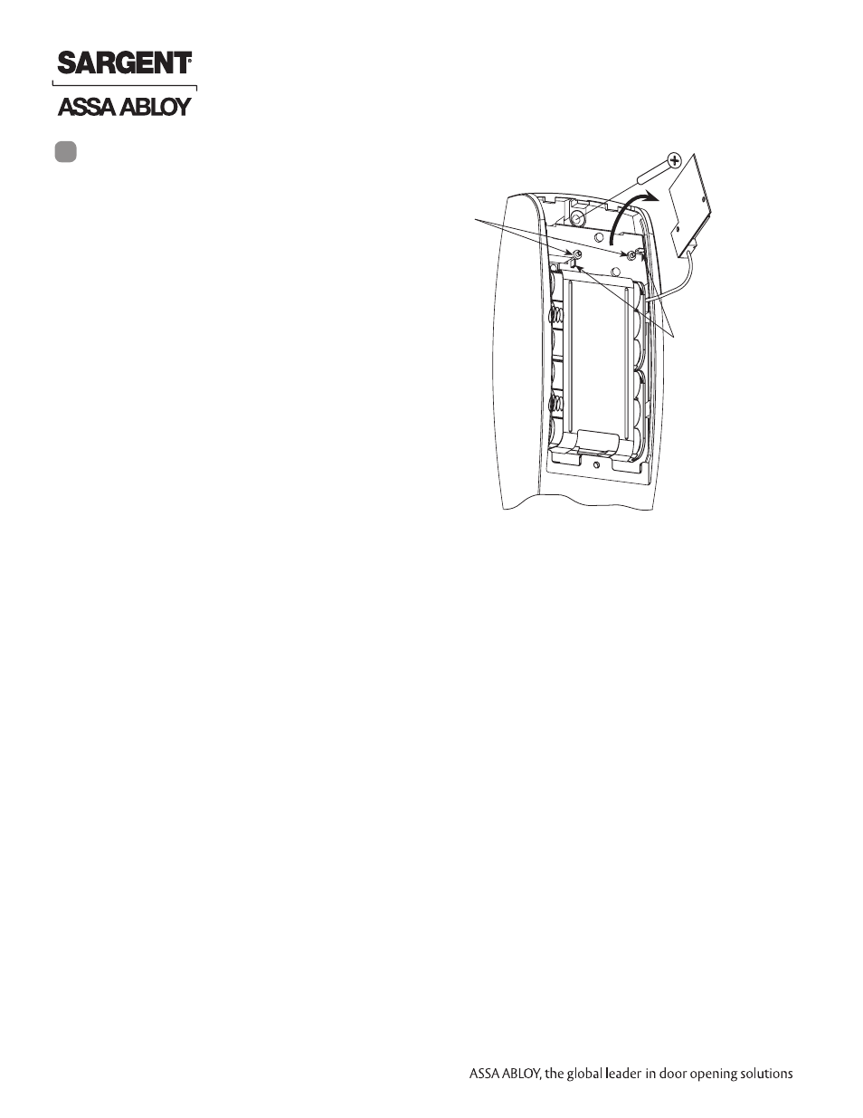
Installation for the RF Technology Lock for
G1-TU, G1-TA, G1-TP is, for the most part,
installed as described in section 6.
In addition:
The antenna board must be carefully
moved to access the upper through-bolt
screw. Care should be taken to prevent
damage to the antenna retaining tabs
during this process (Fig. 7A).
1. Press the two tabs away from the
antenna board and lift the board
off the mounting posts.
2. Insert the flat head through-bolt and
secure the escutcheon in place.
3. After tightening the top through-bolt,
replace the antenna board by placing
it on the mounting posts and pressing
into the retaining tabs.
RF Technology Lock
7
Flathead
Through-bolt
Fig. 7A
Antenna
Board
Mounting
Posts
Antenna
Board
Antenna Board
Retaining Tabs
Controller
Assembly