Tweco 550i Transmig User Manual
Page 33
TRANSMIG 350i, 450i, 550i
Manual 0-5205 3-13
INSTALLATION, OPERATION AND SETUP
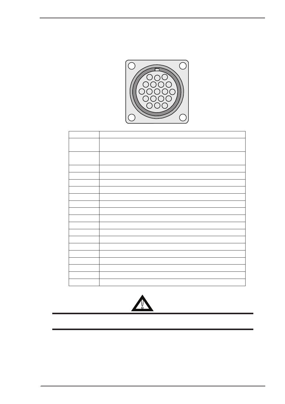
21. 19 Pin Wirefeeder Control Socket
The WIREFEEDER 19 pin receptacle is used to connect a Wirefeeder to the welding Power Source circuitry.
To make connections, align keyway, insert plug, and rotate threaded collar fully clockwise. The socket
information is included in the event the supplied cable is not suitable and it is necessary to wire a plug or
cable to interface with the WIREFEEDER 19 pin receptacle.
A
B
C
D
E F G
H
K
J
L
M
R
P
N
S
T
U
V
A-10637
Socket Pin
Part Number / Description
A
Contactor + (Contact closure is provided between socket
pins A and B to energise the contactor)
B
Contactor - (Contact closure is provided between socket
pins A and B to energise the contactor)
C
Voltage feedback (1V=10V output voltage)
D
Not used
E
Input Supply 110VAC 4A with respect to Socket F (circuit common)
F
42VAC and 110VAC common
G
Chassis Ground (Mains Earth)
H
Remote Voltage Control Potentiometers Maximum
J
Remote Voltage Control Potentiometer Wiper
K
Remote Voltage Control Potentiometers Minimum
L
Control circuit common
M
Arc Established = +15V DC
N
Power Source Select Line (0V = wirefeeder enabled)
P
Not used
R
Not used
S
Input Supply 42VAC 8A with respect to Socket F (circuit common)
T
Not used
U
Current feedback (1V=100A output current)
V
Not used
Table 3-3: 19 Pin Interconnection Control Plug configuration
!
WARNING
The Protective Earth Ground pin G of the control cable is established only when the power source
is properly grounded