Tweco RC6010 User Manual
Page 35
Manual 0-2478
31
APPENDIX
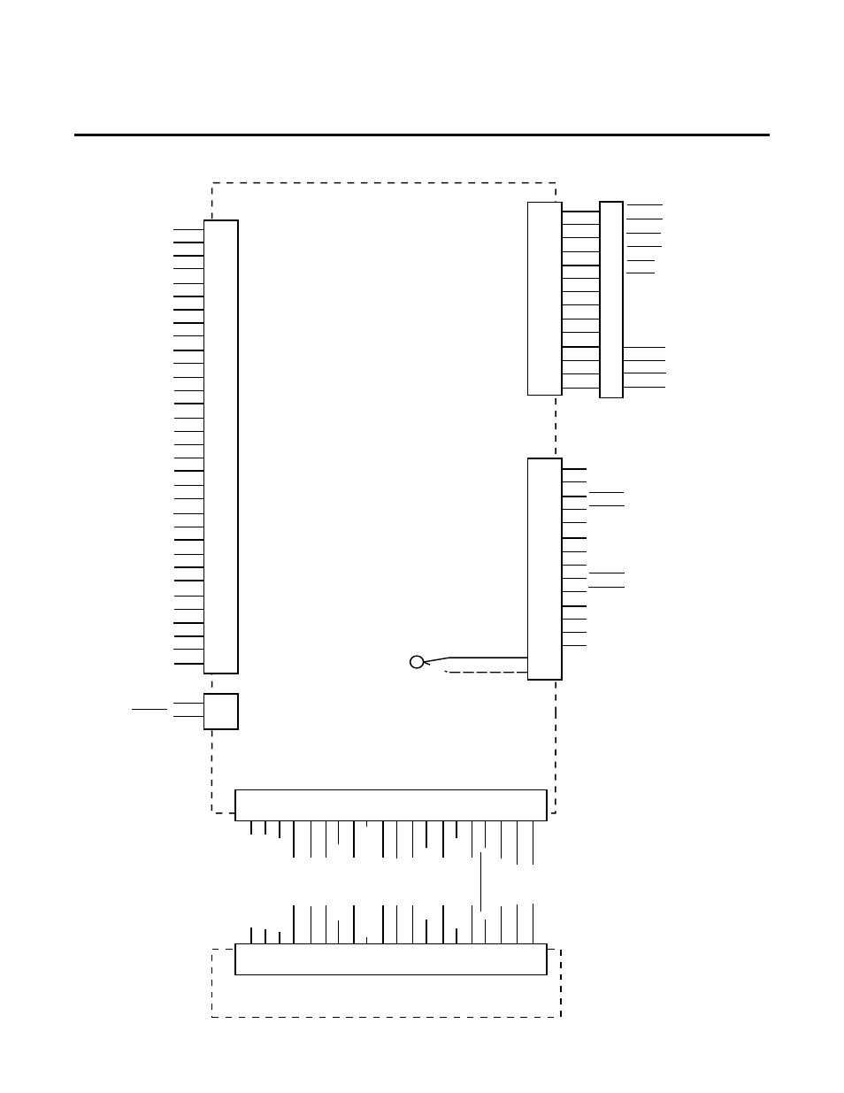
APPENDIX I: REMOTE CONTROL ACCESSORY -
WIRING DIAGRAM
A-00684
PS
J37
Remote Control
PC Board
1
2
3
4
5
6
7
8
9
10
11
12
13
14
15
16
17
20
21
22
23
24
25
26
27
28
29
30
31
32
33
34
35
J9
J6
CNC
J29
1
2
3
4
5
6
7
8
10
11
9
13
12
14
1
2
3
4
5
6
7
8
9
10
11
12
14
16
1
2
3
4
5
6
7
8
9
10
11
12
13
16
14
15
CNC Cable Hard Wired
J5
J7
Standoff Control PC Board
Ribbon Cable Installed Between J5 and Standoff
Control PCB J7 When Standoff Control Is Used
J37
START (Momentary)
START (Momentary) Return
START/STOP
START/STOP Return
Station Select
Station Select Return
Corner Slowdown (CSD)
Corner Slowdown (CSD) Return
E-STOP
OK-To-Move
START (Momentary)
START (Momentary) Return
START/STOP
START/STOP Return
STOP (Momentary)
STOP (Momentary) Return
Station Select
Station Select Return
Corner Slowdown (CSD)
Corner Slowdown (CSD) Return
E-STOP
OK-To-Move
E1
OK-To-Move Select
Jumper Wire
Contacts
24 VAC
Display Signal (+)
Display Signal (-)
START LED
PS ENABLE OFF
POT HI
HI/LOW
POT HI Return
HI/LOW Return
PLASMA START
Remote Installed
PURGE
PURGE Return
+48 V
+48 V Return
ON LED
DEMAND
DEMAND Return
SET
SET Return
POT LOW
POT LOW Return
ENABLE
E-STOP
OK-To-Move
ARC Volt Signal (+)
ARC Volt Signal (-)
+48 V
+48 V Return
ARC Volt Signal (+)
ARC Volt Signal (-)
HI LIFTER Speed
Ground
Ground
Ground
Ground
Ground
Ground
Ground
Ground
Ground
1
2
3
4
7
8
9
10
11
12
13
14
15
16
17
18
19
22
23
24
START
Station Select
Delayed OK-To-Move
OK From PS
START From SC
+48 V
+48 V
Power Supply Cable To
Power Base Unit
CNC Cable With
AMP Connector To
CNC Equipment
or
STOP (Momentary)
STOP (Momentary) Return
PS ENABLE
1
2
3
4
7
8
9
10
11
12
13
14
15
16
17
18
19
22
23
24
1
2
J4
+15 V
ARC ON
Cable To Optional
Arc Hour and
ArcStarts Counters