Tweco RC6010 User Manual
Page 23
Manual 0-2478
19
INSTALLATION PROCEDURES
J29
Pin #
Polarity
Description
10
+
Corner Slowdown (CSD)
11
-
Corner Slowdown (CSD) Return
3
+
START/STOP
4
-
START/STOP Return
5
+
STOP (Momentary)
6
-
STOP (Momentary) Return
7
+
Station Select
8
-
Station Select Return
1
+
START (Momentary)
2
-
START (Momentary) Return
9
-
E-STOP (One side Of Switch)
13
+
E-STOP (Other Side Of Switch)
12
OK-To-Move (One Side Of Signal)
14
OK-To-Move (Other Side Of Signal)
3. CNC Control Cable - Hard Wired (Strain Relief)
NOTE
The supplied CNC cable is a shielded cable. Any
user supplied cable should also be of a shielded type.
The shields must be grounded only at the control-
ler or cutting machine ground.
If the CNC cable from the CNC equipement cannot
be supplied with a mating AMP connector to J29
(CNC) the cable can be hard wired to the Remote
Control Accessory. To wire the cable to the unit use
the following procedure:
a. Remove the cover of the Remote Control to gain
access to the internal connection on the PC board.
b. Feed the control cable through the strain relief at
the rear panel of the Remote Control.
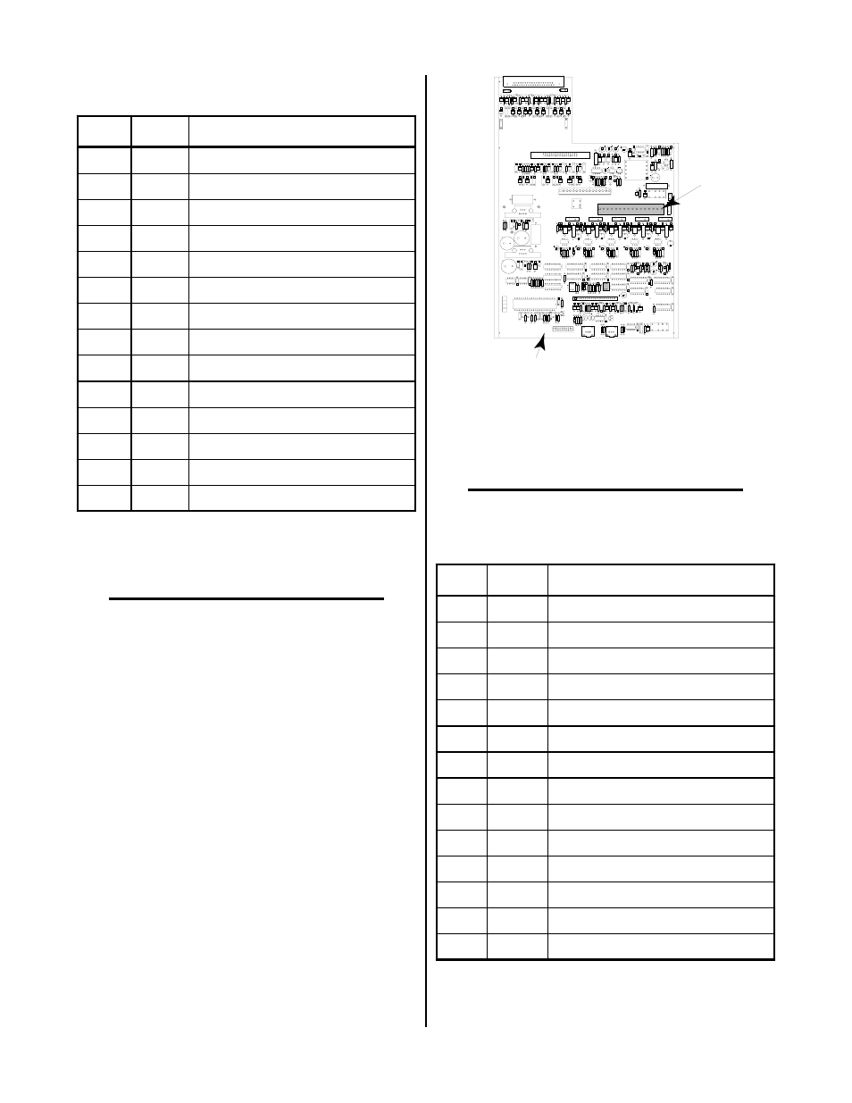
c. Locate the terminal block J6 on the PC board.
Remote Control
PC Board Assembly
A-00681
J6
Figure 3-19 Terminal Block J6 Location
c. Connect the ends of the control cable to J6 on the
PC Board per the following chart:
NOTE
Pins 14 and 15 at J6 are used for OK-To-Move Se-
lection only. Refer to Section 3.08-C for details.
J6
Pin #
Polarity
Description
1
+
Corner Slowdown (CSD)
2
-
Corner Slowdown (CSD) Return
3
+
START/STOP
4
-
START/STOP Return
5
+
STOP (Momentary)
6
-
STOP (Momentary) Return
7
+
Station Select
8
-
Station Select Return
9
+
START (Momentary)
10
-
START (Momentary) Return
11
-
E-STOP (One side Of Switch)
12
+
E-STOP (Other Side Of Switch)
13
OK-To-Move (One Side Of Signal)
16
OK-To-Move (Other Side Of Signal)
d. Tighten the strain relief to secure the control cable.
e. Reinstall the cover to the Remote Control Acces-
sory.