09 external cable connections – Tweco RC6010 User Manual
Page 22
INSTALLATION PROCEDURES
18
Manual 0-2478
A-00720
OK-To-Move
Contact Closure
(NC)
J6-13 or
J29-12
System #1
Remote Control
External AC or DC Voltage
Maximum 115 Volts
Cutting Equipment
Controls
J6-16 or
J29-14
Figure 3-16 Wiring For One System Using External
Voltage
For systems using two or more plasma power supplies
connect the OK-To-Move contacts in series. Both con-
tacts need to be closed, normal condition, to have a com-
pleted circuit. When one plasma supply is not being used,
either by the plasma power supply power, STATION
SELECT, or ENABLE are turned OFF, the contact closure
for that system will be normally closed (NC). The sys-
tem that is turned ON controls the OK-To-Move signal to
the cutting equipment. Connect the external voltage be-
tween one side of each contact closure.
A-00721
OK-To-Move
Contact Closure
(NC)
J6-13 or
J29-12
System #1
Remote Control
OK-To-Move
Contact Closure
(NC)
System #2
Remote Control
Cutting Equipment
Controls
J6-16 or
J29-14
J6-16 or
J29-14
J6-13 or
J29-12
External AC or
DC Voltage
Maximum 115 Volts
Figure 3-17 Wiring For Two Or More Systems
Using External Voltage
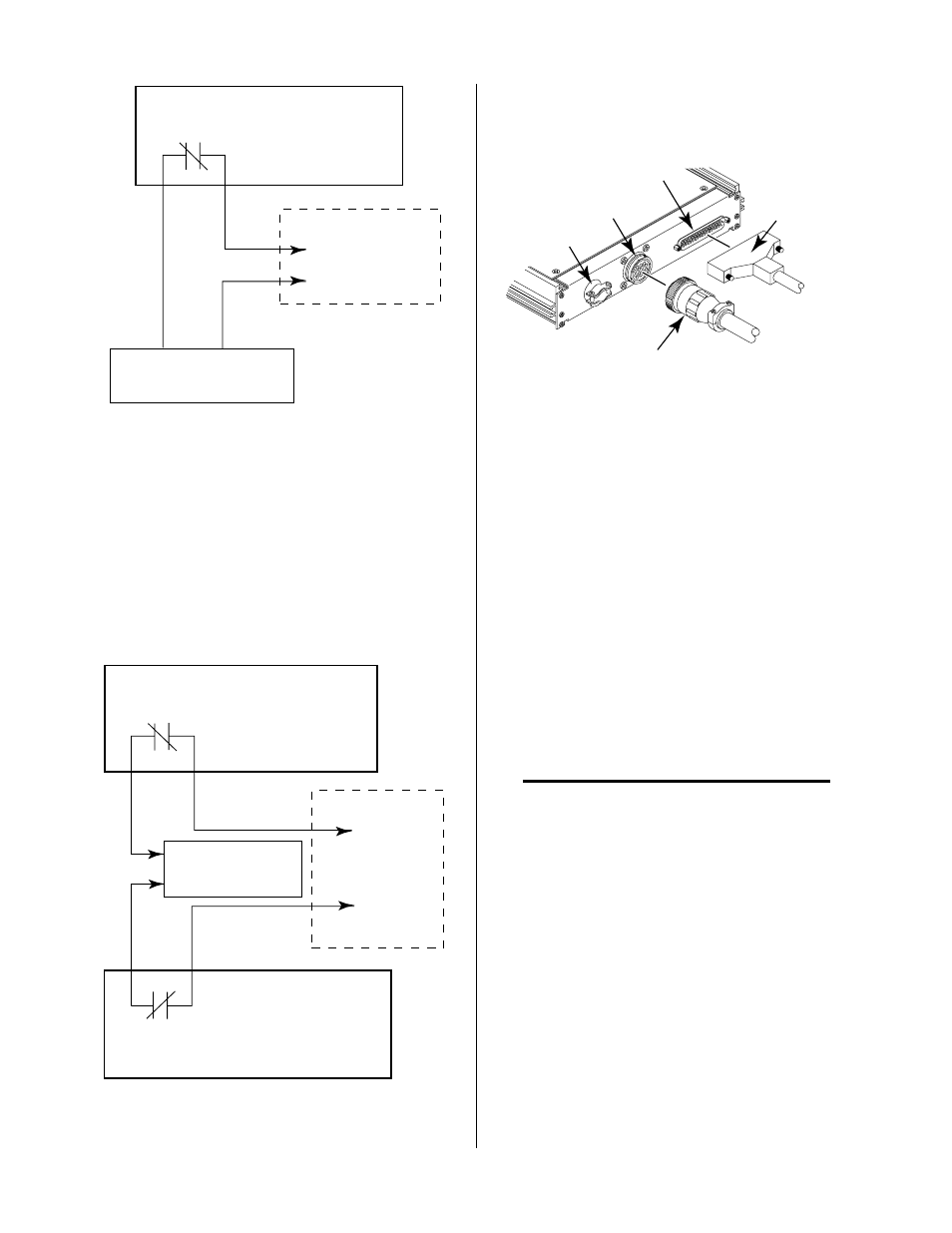
3.09 External Cable Connections
A-00680
CNC
J29
PS
J37
CNC Control
Cable
Power Supply
Cable
Strain Relief
Figure 3-18 Cable Connections
1. Power Supply Cable
Connect the Control Cable to the rear panel of the
Remote Control to the receptacle marked J37 (PS).
Connect the other end of the cable to the rear panel of
the Power Supply for the following systems:
• TD-750 System
Connect cable to the Power Base Unit at recep-
tacle marked J27 (TO REMOTE CONTROL).
• Merlin 3000 and 6000 Systems
Connect cable to the Power Supply at receptacle
marked J15.
2. CNC Control Cable Using AMP Connector
NOTE
The supplied CNC cable is a shielded cable. Any
user supplied cable should also be of a shielded type.
The shields must be grounded only at the control-
ler or cutting machine ground.
1. Connect the CNC Control Cable to the rear panel
of the Remote Control to the AMP receptacle
marked J29 (CNC).
2. Connect the other end of the cable to the CNC Con-
trol Assembly per the following chart (refer to Ap-
pendix III for more information).