Section 4: operation, 01 introduction, 02 functional overview – Tweco RC6010 User Manual
Page 25: 03 operating controls, Figure 4-1 front panel operating controls
Manual 0-2478
21
OPERATION
SECTION 4:
OPERATION
4.01 Introduction
This Section provides a description of the RC6010 Remote
Control Assembly followed by operating procedures.
4.02 Functional Overview
The RC6010 Remote Control Accessory extends the nec-
essary system controls away from the power supply and
is provided with standard machine torch systems.
There are connections available at the Remote Control
Accessory for CNC control, Standoff Control, and Plasma
Power Supply). The inputs and outputs at these connec-
tions allow the various parts of the system to be operated
at one station.
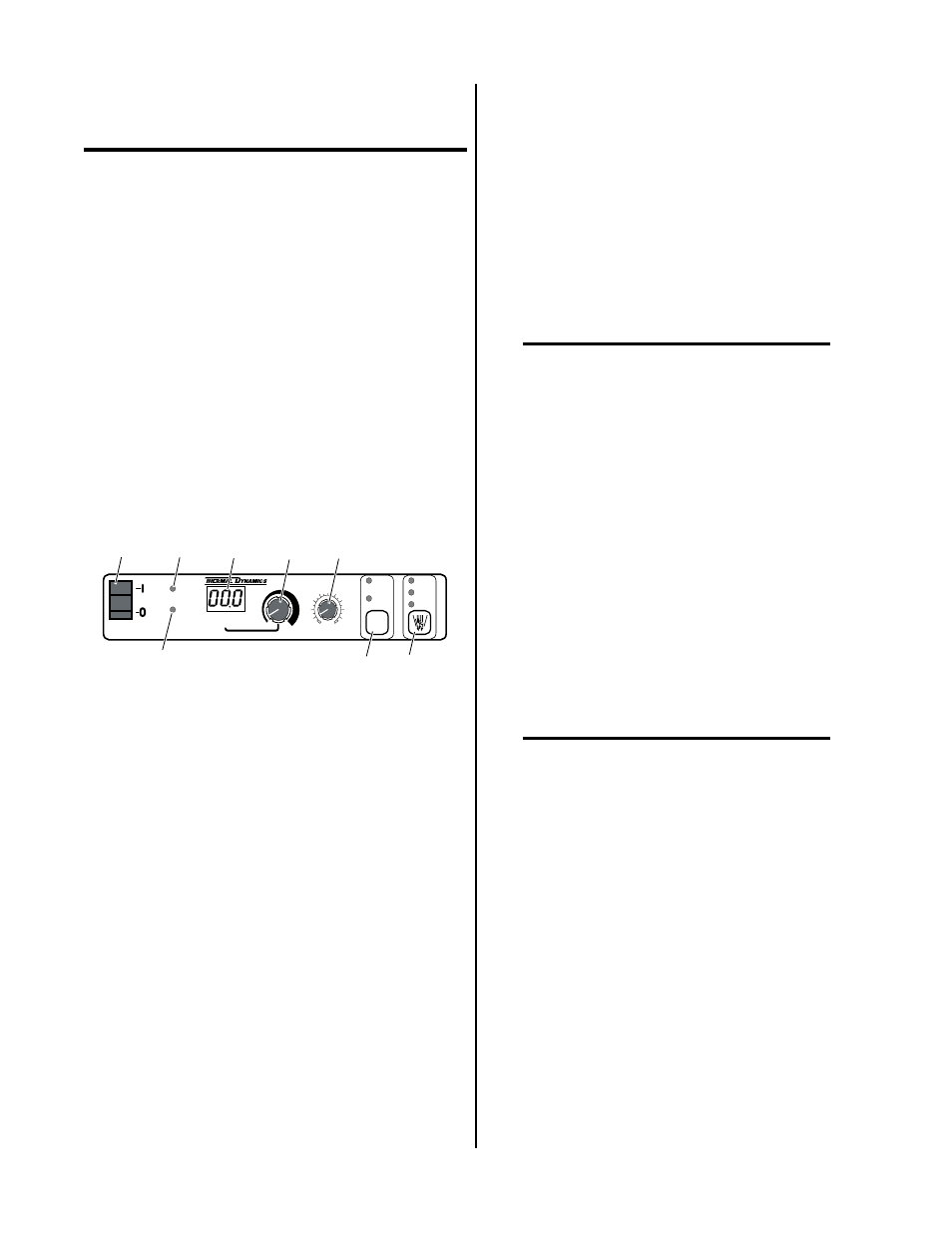
4.03 Operating Controls
OUTPUT AMPS
PLASMA
ENABLE
ON
START
REMOTE POWER SUPPLY CONTROL
CSD
(%)
0
25
75
100
50
TRAVEL
SPEED
125+
IPM
0-125
IPM
RUN
PURGE
SET
1
2
3
4
5
6
7
8
A-00682
Figure 4-1 Front Panel Operating Controls
1. PLASMA ENABLE (On/Off) Switch
Turns on contactor(s) in the Plasma Power Supply to
apply power to the Plasma Power Supply power and
control circuits when in the on (|) position. When the
switch is in the off (0) position the display will be blank
but some indicators may be ON.
2. ON Indicator
Yellow light indicates Plasma Power Supply is en-
abled.
3. START Indicator
Yellow light indicates Plasma Power Supply has re-
ceived start signal from Remote Control.
4. OUTPUT AMPS Meter
Displays actual output during cutting operation. Pre-
view mode displays expected output before starting
a cut according to the current setting. A decimal point
to the right of the display is lit whenever the meter is
in preview mode. All three decimal points remain lit
when displaying corner slowdown output or operat-
ing in corner slowdown mode.
5. Current Control Adjustment
Sets output current level.
6. CSD (%) Corner Slowdown Control Adjustment
Sets corner slowdown (CSD) output as a percentage
of main output.
7. TRAVEL SPEED Switch and Indicators
NOTE
This function used with TD-750 Systems Only.
Pushbutton used to select the pilot pulse rate and re-
start delay for the range of travel speed desired for
the operation. Each time the pushbutton is pressed
the travel speed indicators will toggle between 125+
IPM and 0-125 IPM speeds. The travel speed currently
selected is indicated by the indicator being turned ON.
8. Mode Selection Switch and Indicators
Pushbutton used to select the operating mode of the
system. Each time the pushbutton is pressed the mode
indicators will sequence through RUN, PURGE, and
SET. RUN mode is used for torch operation; PURGE
mode is used for purging the plasma gas line only;
SET mode is used to set the plasma and secondary
gas pressures and flows with Optional Gas Flow Con-
trol. The mode currently selected is indicated by the
indicator being turned ON.
NOTE
Mode cannot be switched from RUN mode during
cut operation.