04 troubleshooting specific problems – Tweco RC6010 User Manual
Page 28
SERVICE
24
Manual 0-2478
5.04 Troubleshooting Specific
Problems
Most of the RC 6010 circuits such as START, OK TO MOVE
and CURRENT CONTROL are critical to the system op-
eration and troubleshooting of them is intergrated into
the Power Supply troubleshooting section. This section
is for circuits not covered there.
NOTE
Any voltage measurements in this section are with
respect to TP1, the Remote Control PC Board com-
mon.
A. Front panel switch for TRAVEL SPEED or RUN/
PURGE/SET doesn’t work
The front panel momentary switches are part of a
membrane panel which connects to the Remote Con-
trol PC Board at J1.
1. Improper connection to PC Board
a. Check J1 for loose connection.
b. Check that connection is not plugged in with
one (or more) pins offset.
2. Normal operation
It is normal that RUN/PURGE/SET can’t be switched
during the pilot or cut sequence.
3. Faulty RUN/PURGE/SET Switch
Measure continuity from Remote Control PC Board
common, TP1, to J1-7 while pressing the switch. It
should be less than 300 ohms.
a. Replace the Front Panel Assembly.
4. Faulty TRAVEL SPEED Switch (See Note)
NOTE
The TRAVEL SPEED circuit isn’t used with the
Merlin Systems.
Measure continuity from Remote Control PC Board
common, TP1, to J1-9 while pressing the switch. It
should be less than 300 ohms.
a. Replace the Front Panel Assembly.
B. One or more front panel indicators will not come
ON
The front panel indicators are part of a membrane
panel which connects to the Remote Control PC Board
at J1. One indicator ON at a time is normal.
1. Improper connection to PC Board
a. Check J1 for loose connection.
b. Check that connection is not plugged in with
one (or more) pins offset.
2. Faulty Remote Control PC Board
C. More than one of the RUN, PURGE, SET indica-
tors are ON
1. Improper connection to PC Board
a. Check J1 for loose connection.
b. Check that connection is not plugged in with
one (or more) pins offset.
2. Faulty indicator or Remote Control PC Board
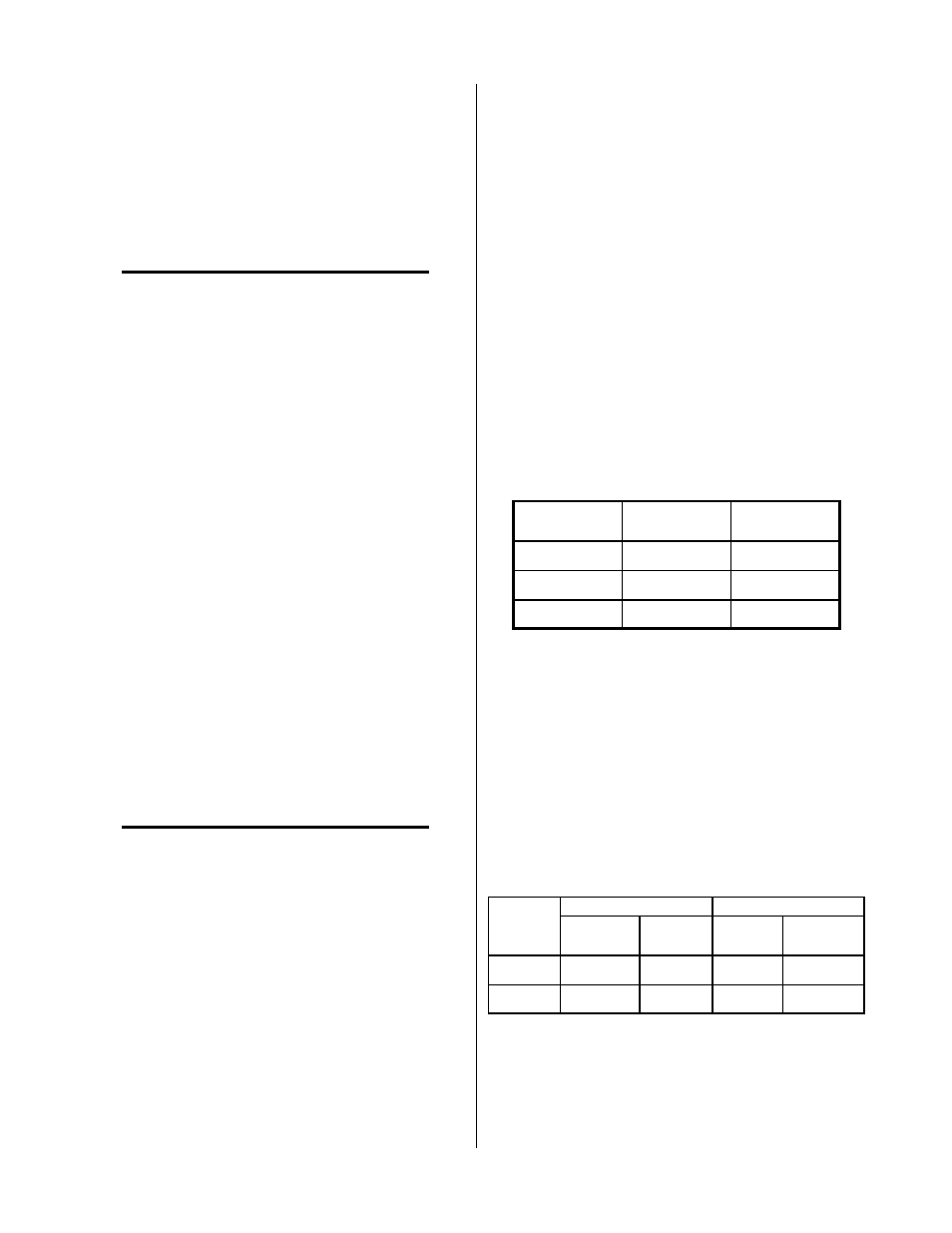
Test the indicators per the following:
With one indicator ON, the anodes of each indica-
tor is at 3.5 V. The cathode of the one indicator
that is ON is 1.2 V and the two indicators that are
OFF are 2 V.
A n o d e
C o n n e c t io n
I n d ica t o r
C a t h o d e
C o n n e c t io n
J 1 -1 1
S E T
J 1 -1 0
J 1 -1 3
P U R G E
J 1 -1 2
J 1 -1 8
R U N
J 1 -1 7
If none of the three indicators are ON the anodes
would go to 5 V and the cathodes of the good ones
would be about 3.5V. The bad indicator would be
near 0 V if open, or 5 V if shorted.
a. If all the cathodes are at 3.5 V then replace the
Remote Control PC Board.
b. If one or more of the cathodes are near 0 V or 5
V, then replace the Front Panel Assembly.
D. START indicator OFF
Normal conditions of the START indicator:
Anode
Cathode
Indicator
Condition
Connection
Voltage
Connection
Voltage
ON
J1-3
About 3.5 V
J1-2
About 1.4 V
OFF
J1-3
5 V
J1-2
4.2 V
1. Faulty Remote Control PC Board
Measure the voltage at J1-3
a. Replace Remote Control PC Board if less than
5V.