Tweco RC6010 User Manual
Page 16
INSTALLATION PROCEDURES
12
Manual 0-2478
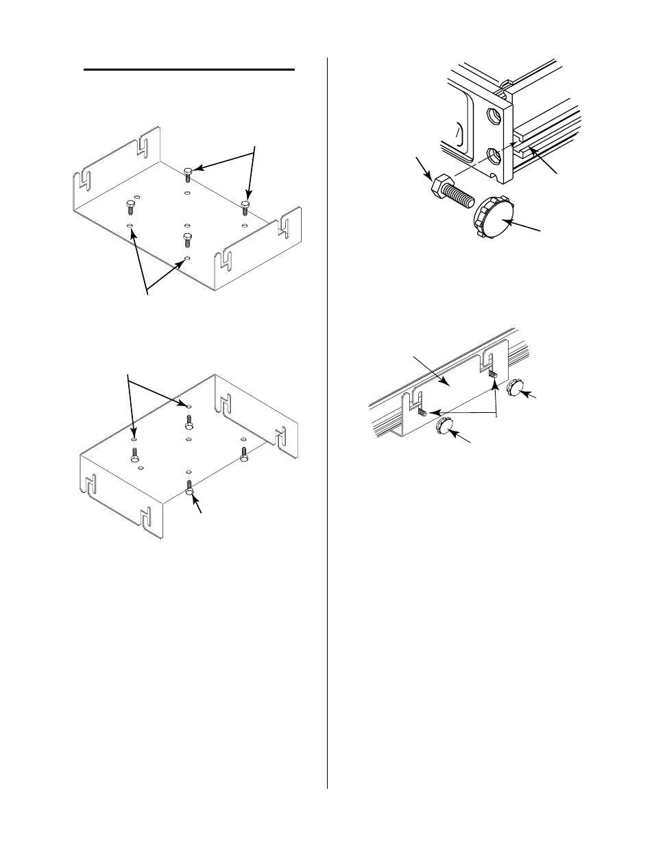
NOTE
There are seven holes provided in the Mounting
Bracket. Use any four holes that are convenient
for the application.
1/4" Mounting Bolts
(Not Supplied)
Mounting Holes
(Seven Places)
A-00671
Figure 3-1 Bracket Mounting On Top Of Surface
A-00672
1/4" Mounting Bolts
(Not Supplied)
Mounting Holes
(Seven Places)
Figure 3-2 Bracket Mounting Underneath Surface
3. Insert two of the #10-32 x 3/8" hex head bolts into
the slots on each side of the Remote Control unit.
The slot prevents the bolts from turning when the
knobs are installed.
RUN
PURGE
SET
Slot
Hex Head Bolt
#10-32 x 3/8"
Knob
A-00673
Figure 3-3 Bolt Installation
4. Set the Remote Control unit into the Mounting
Bracket being sure the four bolts are in the mount-
ing slots.
Knob
Hex Head
Bolts
Knob
Mounting Bracket
A-00674
Figure 3-4 Knob Installation
5. Place one knob on each of the bolts protruding from
the bracket slots.
6. The Remote Control unit can be adjusted for the
best viewing angle. The unit can be tilted up to
10°. Adjust the viewing angle per the following:
a. Loosen the four knobs sercuring the Remote
Control to the Mounting Bracket.
b. Adjust the Remote Control for the desired angle.
c. Tighten all four knobs.
d. If the angle is not correct, loosen knobs, read-
just until proper viewing angle is found, and
retighten all knobs.