Tweco RC6010 User Manual
Page 29
Manual 0-2478
25
SERVICE
2. Faulty Front Panel Assembly or Remote Control PC
Board
Measure the voltage at JI-2
a. If 0 V (open) or 5 V (shorted) then replace Front
Panel Assembly.
b. If voltage is about 4.2 V then replace Remote
Control PC Board.
E. ON indicator OFF
The ON indicator should be ON whenever the
PLASMA ENABLE switch is ON.
PLASMA
ENABLE
Anode
Cathode
Switch
Connection
Voltage
Connection
Voltage
ON
J1-5
About 3.5 V
J1-4
About 1.2 V
OFF
J1-5
0.8 V
J1-4
0 V
1. Faulty connection btween the Remote Control and the
Power Supply
With the PLASMA ENABLE switch to ON, measure
the voltage at J1-4. If it is greater than 3 volts, then
the connection between J1-4 and J50-10 on the Merlin
Switching Control PC Board is faulty.
a. Check and repair connection
2. Faulty Front Panel Assembly
Measure the voltage at J1-4
a. If the voltage at J1-4 is between 1 and 5 volts,
then measure J1-5. If J1-5 is less than 1 volt
higher then J1-4 the ON indicator is shorted,
replace the Front Panel Assembly.
b. If the voltage at J1-4 is 0 volts, then check J1-5.
If J1-5 is high, greater than 12 volts, the ON in-
dicator is open, replace the Front Panel Assem-
bly.
c. If the voltage at J1-5 is less than 1 volt there is a
bad connection between J1-5 and J50-12 on the
Merlin Switching Control PC Board or the
Switching Control PC Board is defective.
A-01246
TRAVEL SPEED
RUN / PURGE / SET
HI
LOW
RUN
PURGE
SET
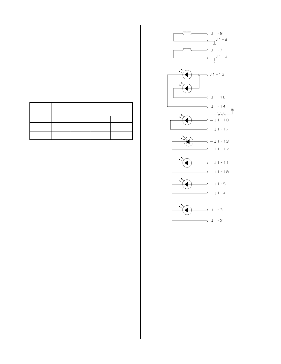
ON
START
Figure 5-1 Indicator Circuit Diagram