08 torch and leads troubleshooting – Tweco Max 300 w-TD-750 User Manual
Page 39
Manual 0-2557
33
SERVICE
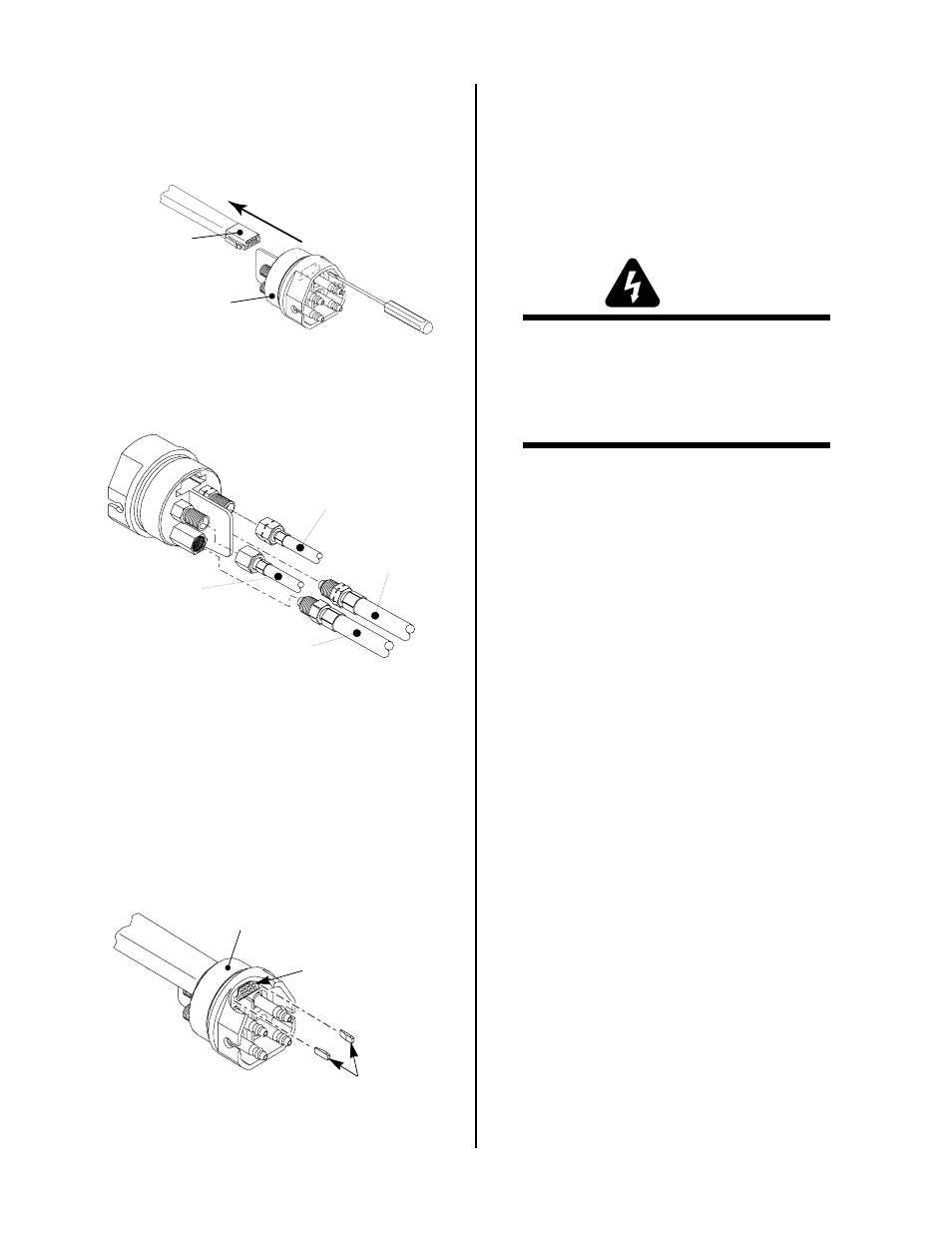
4. Using a small screwdriver, gently push in the tabs
on the side of the signal connector plug towards
the quick disconnect body. Carefully push the con-
nector out through the back of the quick discon-
nect body.
Signal Pin
Connector
Quick Disconnect
Body
A-00265
Figure 5-10 Removing The Signal Connector Plug
5. Disconnect the plasma (+), secondary, coolant sup-
ply (-) and coolant return fittings.
A-00267
Secondary
Connection
Plasma (+)
Connection
(LH Threads)
Coolant Return
Connection
(LH Threads)
Coolant Supply (-)
Connection
Figure 5-11 Disconnecting Leads
C. Reassembling Quick Disconnect Fitting
1. Connect the plasma (+), secondary, coolant supply
(-) and coolant return fittings to the quick discon-
nect body.
2. Insert the signal connector plug in the quick dis-
connect body and install the two white locking tabs
on both sides. The bevel must be towards the sig-
nal connector.
Signal Pin
Connector
Quick Disconnect
Body
A-00273
White Tabs
Figure 5-12 Installing White Locking Tabs
3. Slide the protective boot down onto the quick dis-
connect body.
4. Tighten the three mounting screws to secure the
protective boot onto the quick disconnect body.
5.08 Torch And Leads
Troubleshooting
WARNINGS
Disconnect primary power to the system before
disassembling the torch or torch leads.
DO NOT touch any internal torch parts while the
AC indicator light on the front panel of the Con-
trol Module is ON.
A. Checking Center Insulator
1. Remove the shield cup, tip, gas distributor, and
electrode from the torch.
2. Disconnect the torch leads from the power supply
to isolate the torch from power supply circuits.
3. Using an ohmmeter (set to 10K or higher), check
for continuity between the positive and negative
torch quick disconnect fittings.
If infinite resistance (no continuity) is found the
center insulator is okay. Proceed to paragraph B,
Checking Pilot and Switch Control Wires.
If there is continuity between the two torch quick
disconnect fittings proceed to Step 4.
4. Remove the torch head from the leads (refer to Sec-
tion 5.06, Servicing Machine TorchComponents).
5. With the torch head disconnected from the leads,
measure the resistance between negative cathode
body of the torch head (where the electrode seats)
and the positive anode body of the torch head (the
outer threads where the shield cup seats).
Infinite resistance (no continuity) should be mea-
sured between negative and positive sections of
the torch head.
If any current can flow through the center insula-
tor, the torch head is faulty and must be replaced.
If the torch head is okay, the problem is in the leads
or quick disconnect assembly. Proceed to Step 6.
6. Slide the quick disconnect body, boot, and retain-
ing ring back (refer to Section 5.08, Servicing Torch
Leads Components).