07 servicing torch leads components – Tweco Max 300 w-TD-750 User Manual
Page 38
SERVICE
32
Manual 0-2557
2. Slide the torch adapter down over the leads and
screw the adaptor securely onto the back of the
torch head assembly.
3. Slide the positioning tube down over the leads and
thread it into the torch adaptor on the torch head
assembly.
WARNING
Any uninsulated parts of the two control leads
(green & white wires) must not come in contact
with each other or any other parts of the torch as-
sembly. The torch will activate after the purge at
power on.
4
. Install the front end torch parts.
5.07 Servicing Torch Leads
Components
WARNING
Disconnect primary power to the system before
disassembling the torch or torch leads.
A. Tools Required
(1) 5/64 inch Allen Wrench
(1) 5/8 inch (or Adjustable) Open End Wrench
(2) 11/16 inch (or Adjustable) Open End Wrenches
(1) Small Standard Head Screwdriver
(1) Sharp Probe or Small Needlenose Pliers
(1) Pin Removal Tool
B. Loosening Mounting Screws
To disassemble the quick disconnect connector, use the
following procedure:
1. Disconnect the torch leads from the power supply.
2. Partially loosen each of the mounting screws which
secure the protective boot onto the quick discon-
nect body.
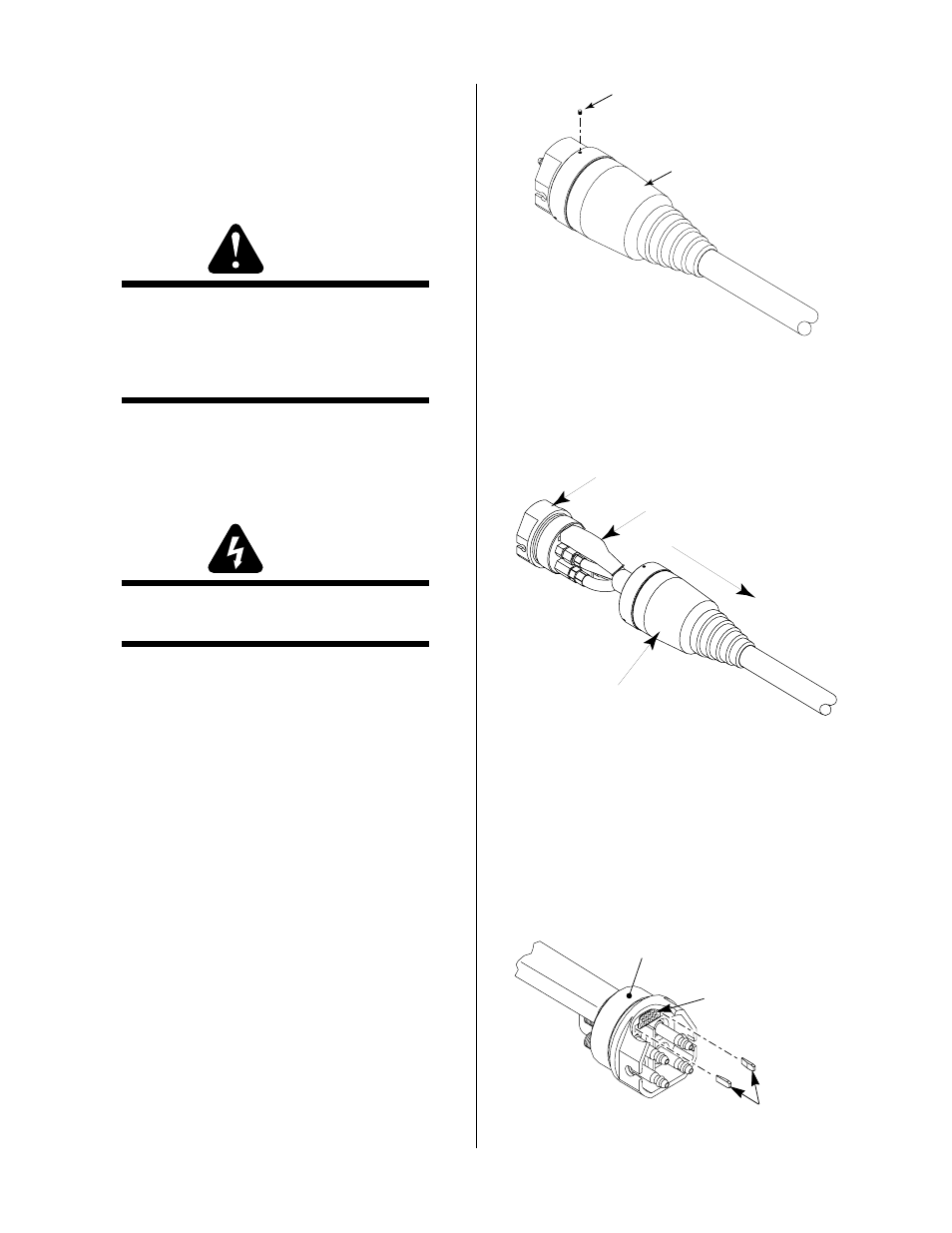
Mounting Screw
(Three Places)
Protective Boot
A-00264
Figure 5-7 Loosing Mounting Screws
C. Disassembling Quick Disconnect Fitting
1. Pull the protective boot from the quick disconnect
body.
A-00266
Protective Boot
Quick Disconnect
Body
Rubber Cover
Figure 5-8 Disassembly Of Connector
2. Slide the protective boot back over the torch leads
to expose the leads connections.
3. Using a pair of needle nose pliers pull the two white
tabs on each side of the signal connector out the
front of the quick disconnect body. These tabs hold
the connector tightly in place to prevent it from
moving.
Signal Pin
Connector
Quick Disconnect
Body
A-00273
White Tabs
Figure 5-9 Removing White Tabs