05 connecting torch, 06 gas selection, 05 connecting torch 3.06 gas selection – Tweco Max 300 w-TD-750 User Manual
Page 20
INSTALLATION PROCEDURES
14
Manual 0-2557
Rack and
Pinion Mounting
Assembly
Square
A-00660
Workpiece
Figure 3-1 Machine Torch Set-Up
3.05 Connecting Torch
WARNING
Disconnect primary power at the source before dis-
assembling the torch or torch leads.
1. Connect the torch leads extension quick discon-
nect fitting onto the receptacle marked TORCH on
the front panel of the Power Base Unit.
NOTE
The Power Base Unit must be installed in the sys-
tem according to the Power Base Unit Operating
Manual (Catalog No. 0-2474) supplied with the
Power Base Unit.
2. Connect the other end of the torch leads extension
quick disconnect fitting onto the receptacle, pin
type, on the input panel of the Arc Starter Box.
NOTE
The Arc Starter Box must be installed in the sys-
tem according to the Arc Starter Box Instruction
Manual (Catalog No. 0-2475) supplied with the
Arc Starter Box.
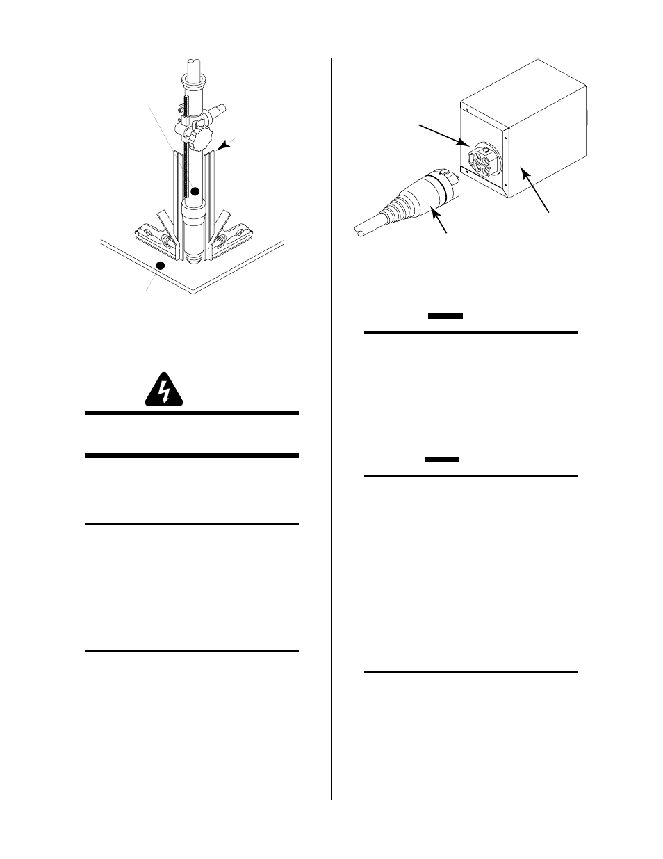
3. Connect the torch with short leads attached to the
quick disconnect receptacle, socket type, on the
output panel of the Arc Starter Box.
A-00653
Torch Leads
Torch Connector
Arc Starter Box
Figure 3-2 Torch Connection to Arc Starter Box
2. Check the torch for proper parts assembly.
CAUTION
The torch parts (gas distributor, electrode, tip, and
shield cup) must correspond with plasma and sec-
ondary selection, output current level, and type of
operation (cutting or gouging). Refer to Section
4.04, Torch Parts Selection.
3.06 Gas Selection
CAUTIONS
Maximum input gas pressure must not exceed 125
psi (8.6 BAR)
Air supply must be free of oil, moisture, and other
contaminants. Excessive oil and moisture may
cause double-arcing, rapid tip wear, or even com-
plete torch failure. Contaminants may cause poor
cutting performance and rapid electrode wear.
The type of operation will determine the best gases to be
used. Refer to the following and select the plasma and
secondary gases that best fit the operation(s):
A. Plasma Gases
NOTE
Refer to Section 2.03, Specifications & Design Fea-
tures, for proper gas pressure and flow rate.
1. Air Plasma
• Most often used on ferrous or carbon base materials
to obtain good quality at faster cutting speeds.
• Air plasma is normally used with air secondary.