05 cut quality – Tweco Max 300 w-TD-750 User Manual
Page 25
Manual 0-2557
19
OPERATION
To change the torch parts for a different operation use
the following procedure (See Note):
NOTE
A multi-purpose wrench is supplied for changing
the tip, electrode and gas distributor in the torch
head.
Multi-Purpose Wrench
(Catalog Number 20-0001)
Used for Electrodes
Used for 11/16" ( 17.5 mm)
Across Tip Flats
Gas Distributor Notch
Used with 11/16" (17.5 mm)Tip
Used for 5/8" ( 15.9 mm)
Across Tip Flats
Gas Distributor Notch
Used with 5/8" (15.9 mm)Tip
This Side
Towards Torch
A-01639
Figure 4-2 Multi-Purpose Wrench
1. Unscrew and remove the shield cup from the torch
head.
Torch Head
Electrode
Tip
Gas Distributor
Shield Cup
A-00661
Figure 4-3 Liquid Cooled Maximizer 300 Torch
Parts
2. Using the multi-purpose wrench (5/8 inch slot) re-
move the tip.
3. Tilt the torch head to remove the gas distributor. The
end of the multi-purpose wrench can be used to help
remove the gas distributor.
4. Using the multi-purpose wrench (electrode area) re-
move the electrode.
5
. Install the desired electrode for the operation into the
torch head. The circular area around the wrench used
for electrodes will also align the electrode in the torch
head. This will prevent installing electrodes on an
angle and cross threading the electrode in the torch
head.
6. Install the desired gas distributor and tip for the op-
eration into the torch head.
NOTE
Be careful not to overtighten the electrode and tip
when reinstalling.
7. Hand tighten the shield cup until it is seated on the
torch head. If resistance is felt when installing the
cup, check the threads before proceeding.
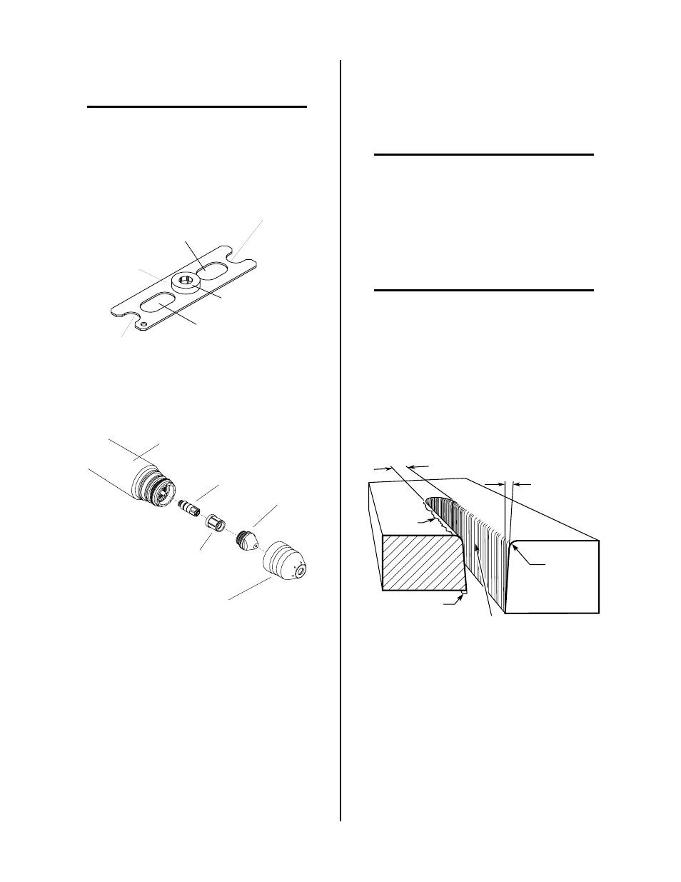
4.05 Cut Quality
NOTE
Cut quality depends heavily on set-up and param-
eters such as torch standoff, alignment with the
workpiece, cutting speed, gas pressures, and op-
erator ability.
Cut quality requirements differ depending on applica-
tion. For instance, nitride build-up and bevel angle may
be major factors when the surface will be welded after
cutting. Dross-free cutting is important when finish cut
quality is desired to avoid a secondary cleaning opera-
tion. The following cut quality characteristics are illus-
trated in Figure 4-4:
Kerf Width
Cut Surface
Bevel Angle
Top Edge
Rounding
Cut Surface
Drag Lines
Dross
Build-Up
Top
Spatter
A-00007
Figure 4-4 Cut Quality Characteristics
A. Cut Surface
The desired or specified condition (smooth or rough)
of the face of the cut.
B. Nitride Build-Up
Nitride deposits can be left on the surface of the cut
when nitrogen is present in the plasma gas stream.
These buildups may create difficulties if the material
is to be welded after the cutting process.