T1 t2 t3, L1 l2 l3 – Tweco 51 with SL100SV CutMaster User Manual
Page 95
Manual 0-4640
5-31
SERVICE
5
D. Main Input Power Test
WARNING
The following tests must be performed with the power supply connected to primary input power. There are extremely
dangerous voltage and power levels present inside this unit. Do not attempt to diagnose or repair without proper
training in power electronics measurement and troubleshooting techniques.
Reconnect power and observe proper start-up procedure. AC indicator on the Front Panel should be ON. If indicator is OFF there
is no voltage to the Power Supply or an overvoltage condition exists.
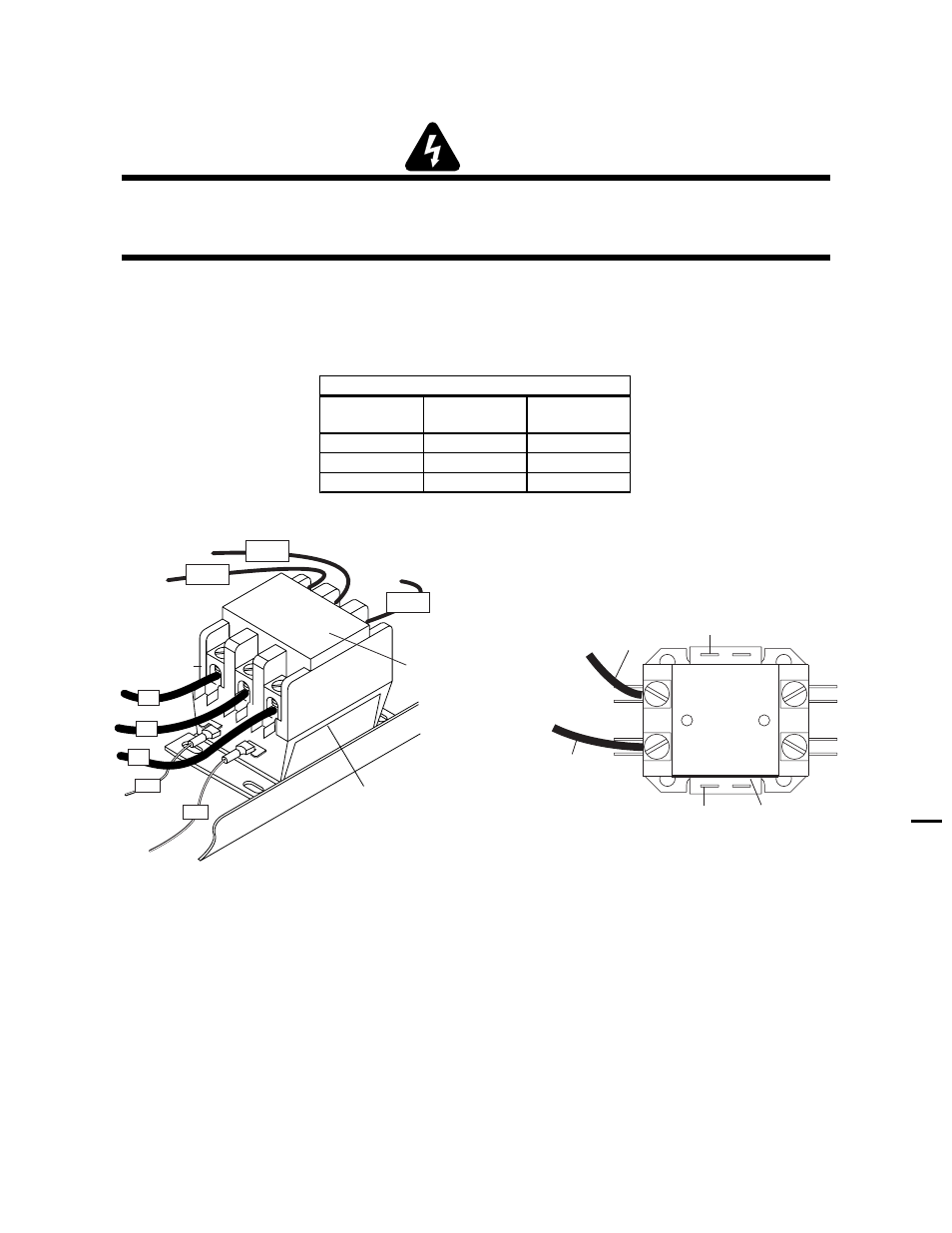
1. If AC indicator on Front Panel is OFF, check for proper AC input voltage between input cables on the Main Contactor.
Input voltage should be as shown in the following chart. If not, check for proper voltage at the main power source.
Input
Power
Test Points
Voltage
Range
208/230V
L1, L2
187-253VAC
400V
L1, L3
360-440VAC
460V
L1, L3
414-506VAC
CutMaster 51 Input Contactor Voltage Ranges
A-03224
Main Contactor
L1 L2 L3
T1
T2
T3
To E3
Connections to
Main PCB
To E1
To E2
Input Side
Label
#11
#12
L3
L2
L1
A-03223
Input
Cable (L1)
Input
Cable (L2)
Label
Wire #11
Wire #12
Main Input Contactor (460-Volt Three-Phase Input Power Shown) 208/230-Volt Main Input Contactor
2. Check for approximately 28 VAC on coil of contactor between wires # 11 and #12.
a. If voltage is correct, replace main contactor. If voltage is incorrect, replace Main PC Board.