Tweco 51 with SL100SV CutMaster User Manual
Page 93
Manual 0-4640
5-29
SERVICE
5
C. Diode Module Board Tests
WARNING
Disconnect primary power at the source before taking any resistance checks.
1. Input Diode Test
a. Disconnect input AC power.
b. Check Input Diode for shorted input diode. With an ohmmeter set on the diode range make the following checks from
Main PC Board to Input Diode:
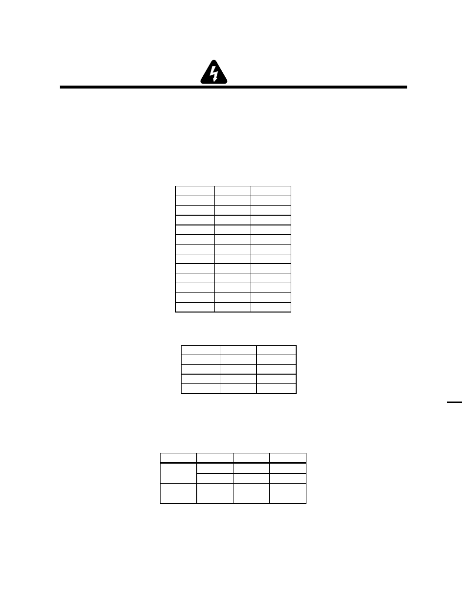
For 400-Volt and 460-Volt Power Supplies:
Meter (+) Meter (-) Indication
E1
E11
Diode Drop
E11
E1
Open
E2
E11
Diode Drop
E11
E2
Open
E3
E11
Diode Drop
E11
E3
Open
E12
E1
Diode Drop
E1
E12
Open
E12
E2
Diode Drop
E2
E12
Open
E12
E3
Diode Drop
E3
E12
Open
For 208/230-Volt Power Supplies:
Meter (+) Meter (-) Indication
E2
E11
Diode Drop
E11
E2
Open
E12
E2
Diode Drop
E2
E12
Open
c. The meter should indicate a diode drop in one direction and an open in the other direction for each check. Replace the
Input Diode Module Board if the readings do not match the chart.
d. If Input Diode Module Board is shorted, make the following checks with an ohmmeter at the Main Contactor (W1):
Meter (+)
Meter (-) Indication
L1
T1
Open
L2
T2
Open
400/460V
Only
L2
T1
Open
All
Voltages
If any test has resistance, then replace the Main Contactor.