Thermostat wiring, Compatible sensors – tekmar 553 Thermostat Installation User Manual
Page 6
© 2014
553_D - 09/14
6 of 52
A Watts Water Technologies Company
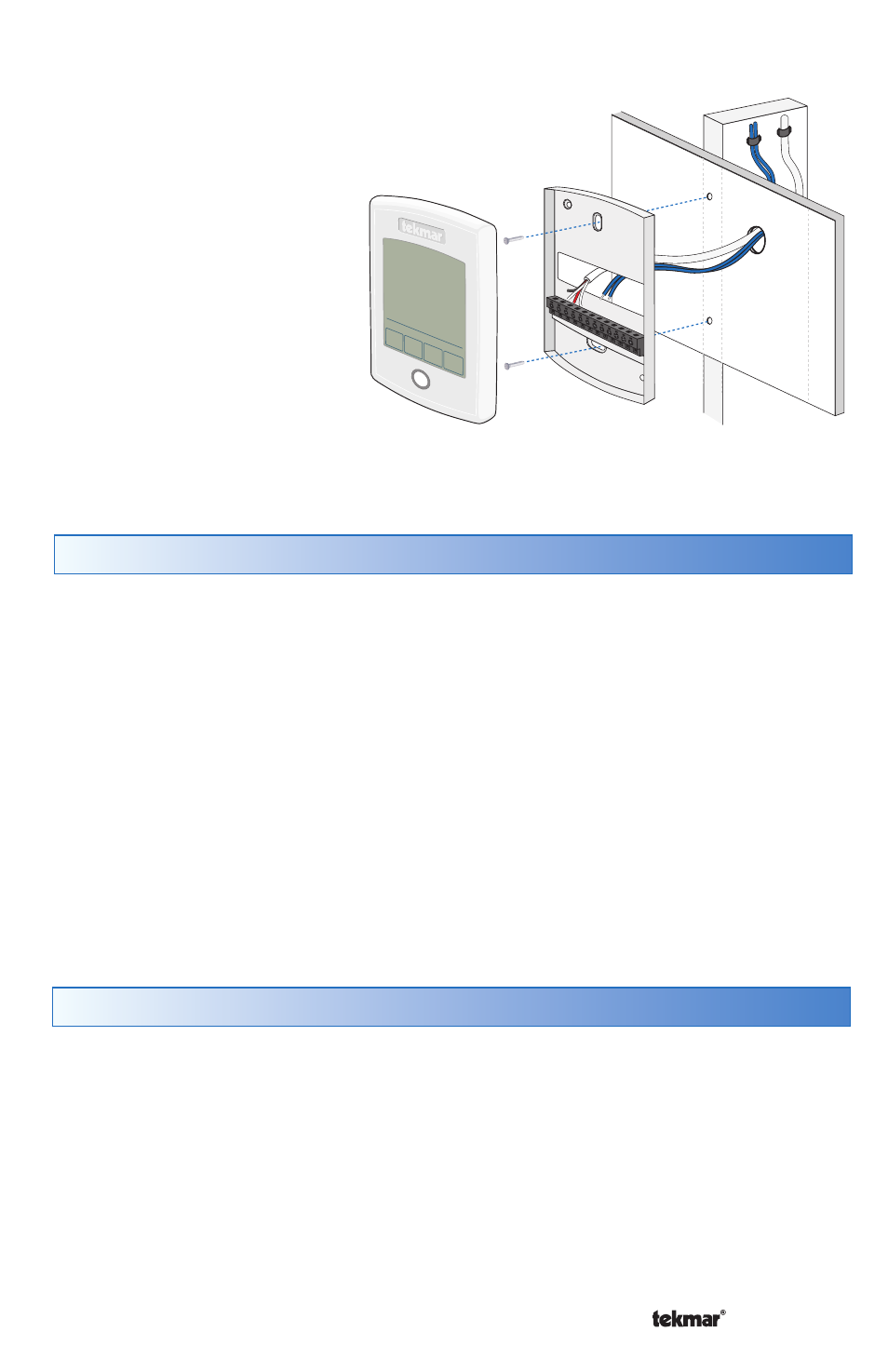
Wall
Stud
Thermostat
Front
Thermostat
Base
If a gang box is not used:
Feed the wiring through the
large hole in the thermostat
base.
Mount the thermostat base
directly to the wall.
Use screws in the screw holes
to fasten the thermostat to
the wall. At least one of the
screws should enter a wall
stud or similar rigid material.
Terminate wiring to the
wiring strip.
Push the thermostat front
onto the thermostat base.
•
•
•
•
•
Thermostat Wiring
The thermostat can be wired in three different ways.
Stand Alone - Similar to tekmarNet
®
4 wiring with tN4 wiring terminal not used. First
stage heating relay (Rh - W1) can be wired directly to switching relays.
tekmarNet
®
4 - Allows the thermostat to be wired using 4 wires to a tN4 Wiring Center
or Zone Manager point-to-point. Alternatively, the thermostat can operate the heating
and cooling equipment locally and the tN4 communication bus can be daisey-chained
from one thermostat to another.
tekmarNet
®
2 - Allows the thermostat to be wired point-to-point using 2 wires to a tN2
Wiring Center, House Control, or Zone Manager. This allows easy wiring for retrofit
applications.
Application specific wiring diagrams are provided in the 553_A brochure.
Compatible Sensors
The thermostat is compatible with Indoor Sensor type 076, 077, 084, Slab Sensor
type 072, 073, 079, Outdoor Sensor type 070, Universal Sensor 082 and Duct Sensor
type 083.