tekmar 544 Thermostat Installation User Manual
Page 24
© 2008
D 544 - 07/08
24 of 36
Heating Operation
Section F
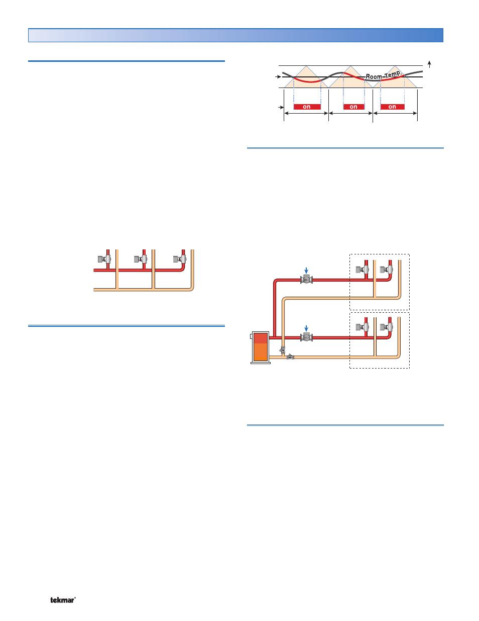
One-Stage PWM Heating
W
a
rmer
Set
Heat
Cycle Length
Heat
Reset Water
Temperature
100%
On Time
85%
On Time
90%
On Time
Indoor Temperature Feedback
Indoor feedback applies when the thermostat is connected to
a tN4 network with a tN4 System Control. Indoor temperature
feedback fine tunes the water temperature of the system
based on the requirements of the thermostats.
Each thermostat tells the tN4 System Control the water
temperature that it requires to heat its zone.
•
• If the zone is becoming too cool, the thermostat asks
for a higher water temperature.
•
• If the zone is becoming too warm, the thermostat asks
for a cooler water temperature.
The tN4 System Control provides the highest water
temperature required by all of the thermostats.
•
• The thermostat with the highest water temperature
requirement stays on 100% of its cycle.
•
• The remaining thermostats stay on for a percentage of
their cycles.
One Stage Heating
Room Sensor Only
When operating with only an room sensor, the on time for
the Heat 1 relay is calculated to satisfy the requirements
of the room sensor.
Floor Sensor Only
When operation with only a floor sensor, the on time for
the Heat 1 relay is calculated to satisfy the requirements
of the floor sensor. The floor temperature varies between
the floor minimum and the floor maximum settings.
Note: Operation with only a floor sensor can lead to either
overheating or underheating of the space.
Room and Floor Sensor
When operating with both a room and floor sensor, the
thermostat calculates an on time for the Heat 1 relay to
satisfy the floor sensor and an on time to satisfy the room
sensor. The Heat 1 relay operates for the longer of these
two on times.
During light heating loads, overheating can occur due to
the minimum floor temperature setting.
During heavy heating loads, the maximum floor temperature
setting limits the on time of the Heat 1 relay. In this situation,
underheating can occur.
Zone Group
Heat 1 Pump = OFF
Zone Manager: Zone Group DIP = On
Operated by
Zone Manager
Operated by
tN4 System Control
Heat 1 Pump = On
Zone Manager: Zone Group DIP = OFF
Zone Group
System Pump Operation
When a tN4 System Control is used, each tN4 bus has a
system pump.
•
• If the tN4 bus’s system pump must turn on when the
Heat 1 relay is on, set the H1 Pump setting in the Adjust
menu to On.
Thermal Motor Zone Valves
When using a thermal motor zone valve, system pump
operation must be delayed to allow the thermal motor zone
valve to fully open.
•
• When thermal motor zone valves are used set the Heat
1 Delay setting to On.