tekmar 371 House Control User Manual
Page 17
17
During the test routine, the test sequence can be paused by pressing the
Test button. The test sequence remains paused at that point
for up to 5 minutes. If the
Test button is not pressed again while the test sequence is paused, the control exits the entire test routine.
Once the test sequence is paused, the
Test button can be pressed again to skip to the next step. This can also be used to rapidly
skip through the test sequence. To reach the desired step, repeatedly press and release the
Test button until the appropriate device
and indicator light turn on.
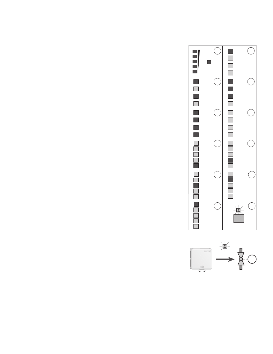
Step 1 -
If the DIP switch is set to
Var. Speed and there is at least one DIP switch set
to
Mixing, the variable speed injection pump is ramped up to 100% over 10
seconds. If the DIP switch is set to
Floating, the open relay is turned on for 10
seconds. If you wish to run the mixing valve fully open, pause the test routine
at this time.
Step 2 -
The
DHW Pmp relay is turned on.
Step 3 -
The
Sys P2 relay is turned on.
Step 4 -
The
Sys P1 relay is turned on.
Step 5 -
The
Boiler relay is turned on.
Step 6 -
The
DHW Pmp, Sys P1, Sys P2, Boiler and Variable Speed Injection Pump are
turned off. If the DIP switch is set to
Floating, the close relay is turned on.
Step 7 -
If the DIP switch is set to
Var. Speed and an RTU / Indoor Sensor is connected
to terminals
Com Sen — RTU 5 (9 and 12), the control turns on the zone 5 relay
for 10 seconds.
Step 8 -
If the DIP switch is set to
Var. Speed and an RTU or Indoor Sensor is connected
to the terminals
Com Sen — RTU 4 (9 and 11), the control turns on the zone
4 relay for 10 seconds.
Step 9 -
If an RTU or Indoor Sensor is connected to the terminals
Com Sen — RTU 3
(9 and 10), the control turns on the zone
3 relay for 10 seconds.
Step 10 - Once the zone 3 relay is turned off, the control follows a similar procedure to
test the zone
2 relay. If an RTU or Indoor Sensor is not connected to the
terminals
Com Sen — RTU 2 (6 and 8), the control skips this step.
Step 11 - Once the zone 2 relay is turned off, the control tests the zone 1 relay. If the DIP
switch is set to
Zone 1 Heat, the control follows a similar procedure as above
to test the zone
1 relay. If the DIP switch is set to Zone 1 Cool, the control will
also turn on the zone
1 relay for 10 seconds.
Step 12 - After the test sequence is complete, the Test light begins flashing and the
control enters a fast mode of operation. During this time, the control is much
more responsive to setting adjustments. If the dial on an RTU is turned up, the
zone relay should turn on immediately. After fifteen minutes, the control reverts
back to normal operating conditions and the zone on times are based on the
average indoor temperatures during the previous 15 minute cycle.
Manual Test
While the control is in the fast mode of operation and the Test light is flashing, check that
each RTU operates the proper zone valve or zone pump. Turn up the RTU dial to turn the
zone on, turn the dial down to turn the zone off. If an Indoor Sensor is used, a cold spray
to the sensor will turn the zone on.
Indicator Lights "On"
Power
• 120 V (ac) power is applied to the control and the control
is energized.
DHW Demand
• The DHW tank is requesting heat.
Setpoint Demand
• Setpoint operation is required.
WWSD
• Heat is not required in the heating system.
Maximum Supply
• The supply temperature is approaching the
Max. System Supply dial setting and the 371 will not increase the
supply temperature any further.
Minimum Boiler
• The supply temperature from the boiler is below the
Min. Boiler Supply dial setting and the 371 is reducing the
load on the boiler in order to increase the boiler supply temperature as fast as possible.
DHW Pmp
• The relay contacts between
DHW Pmp — Power L (4 and 22) are closed and the DHW pump should be running.
90
70
50
30
10
2
1
4
3
6
5
8
7
10
9
12
Test
11
Zone 4 /
Open
4
System
Pump 2
Boiler
System
Pump 1
DHW
Pump
System
Pump 2
Boiler
System
Pump 1
DHW
Pump
System
Pump 2
Boiler
System
Pump 1
DHW
Pump
System
Pump 2
Boiler
System
Pump 1
DHW
Pump
System
Pump 2
Boiler
System
Pump 1
DHW
Pump
Zone 3
Zone 2
Zone 1 /
Cool
1
2
3
4
5
Zone 4 /
Open
Zone 5 /
Close
Zone 3
Zone 2
Zone 1 /
Cool
1
2
3
4
5
Zone 4 /
Open
Zone 5 /
Close
Zone 3
Zone 2
Zone 1 /
Cool
1
2
3
4
5
Zone 4 /
Open
Zone 5 /
Close
Zone 3
Zone 2
Zone 1 /
Cool
1
2
3
4
5
Zone 4 /
Open
Zone 5 /
Close
Zone 3
Zone 2
Zone 1 /
Cool
1
2
3
4
5
Zone 4 /
Open
Zone 5 /
Close
Adjusting RTU settings provides an immediate
response for the first 15 minutes only.
70
M
Test