tekmar 371 House Control User Manual
Page 11
11
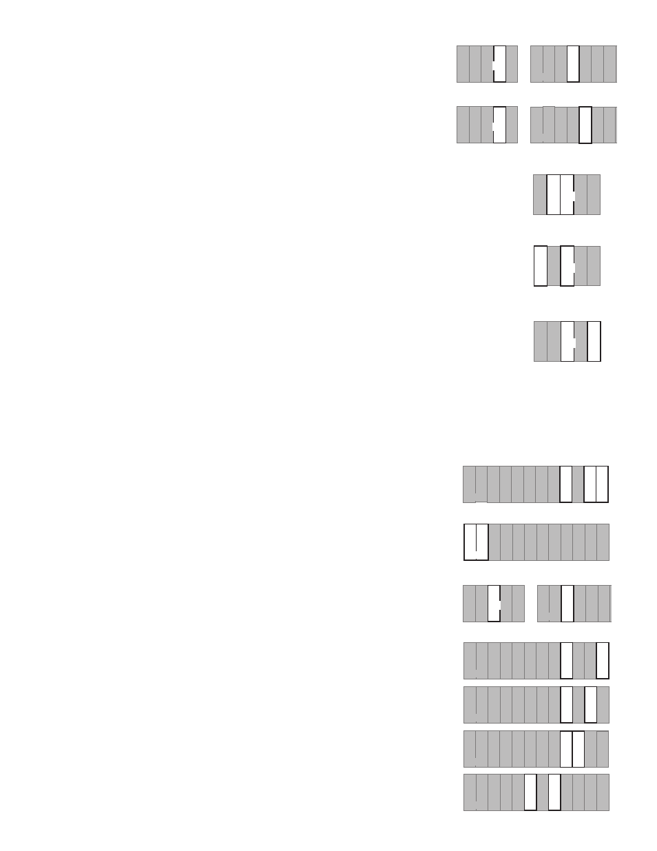
DHW Demand
If a DHW demand is used, connect the switched wire from the DHW demand circuit to
terminal
DHW Dem (23). When 120 V (ac) relative to Neutral (N) is applied to this
terminal, the control recognizes a DHW demand.
Setpoint Demand
If a setpoint demand is used, connect the switched wire from the setpoint demand
circuit to terminal
Setp Dem (24). When 120 V (ac) relative to Neutral (N) is applied to
this terminal, the control recognizes a setpoint demand.
Output Connections
Boiler System Pump (P1)
Connect one wire from the boiler system pump to the
Sys P1 (2) terminal on the control. The other wire
on the boiler system pump must be connected to the
Neutral (N) side of the 120 V (ac) power supply. The
control closes a dry relay contact between
Sys P1 — Power L (2 and 4) when operation of the boiler system
pump is required.
Mixing System Pump (P2)
Connect one wire from the mixing system pump to the
Sys P2 (1) terminal on the control. The other wire
on the mixing system pump must be connected to the
Neutral (N) side of the 120 V (ac) power supply.
The control closes a dry relay contact between
Sys P2 — Power L (1 and 4) when operation of the mixing
system pump is required.
Variable Speed Injection Pump
The 371 can vary the speed of a permanent capacitor, impedance protected or equivalent pump motor
that has a locked rotor current of less than 2.4 A. Most small wet rotor circulators are suitable as described
in Essay E 021.
The variable speed output must not be used on pumps which have a centrifugal switch.
The 371 has an internal overload protection fuse which is rated at 2.5 A 250 V (ac). This fuse is not field
replaceable. Contact your tekmar sales representative for details on the return and repair procedures if
this fuse is blown.
Connect one wire from the variable speed injection pump to the
Var. Pmp (5) terminal on the control. The
other wire on the variable speed injection pump must be connected to the
Neutral (N) side of the 120 V
(ac) power supply, or to L2 for a 240 V (ac) power supply. The control varies the power to the pump in order
to change its speed.
Mixing Valve Actuator
Connect one side of the 24 V (ac) circuit to terminal
Com 3-5 (28). The output relay Opn
4 (30) is then connected to the open terminal of the actuating motor and the output relay
Cls 5 (31) is connected to the close terminal of the actuating motor.
Boiler
Connect the 120 V (ac) or 24 V (ac) Boiler circuit to terminals
Boiler — Boiler (20 and
21). The 371 closes a dry relay contact between these terminals when boiler operation
is required.
DHW Pump
Connect one wire from the DHW pump to the
DHW Pmp (22) on the control. The other
wire on the DHW pump must be connected to the
Neutral (N) side of the 120 V (ac)
power supply. The control closes a dry relay contact between the
Power L— DHW Pmp
(4 and 23) terminals when DHW heating is required.
Zone Pumps and Zone Valves
It is best to start the heating zones at output relay
5 and work towards the output relay 1.
• If Zone 5 is used for heating, connect the Zone 5 Pump or Valve circuit to the
Com
3-5 — 5 (28 and 31) terminals on the control.
• If Zone 4 is used for heating, connect the Zone 4 Pump or Valve circuit to the
Com
3-5 — 4 (28 and 30) terminals on the control.
• If Zone 3 is used, connect the Zone 3 Pump or Valve circuit to the
Com 3-5 — 3
(28 and 29) terminals on the control.
• If Zone 2 is used, connect the Zone 2 Pump or Valve circuit to the
Com 1-2 — 2
(25 and 27) terminals on the control.
5
4
2 3
N
L
Sys
P 1
Var.
Pmp
Power
1
Sys
P 2
23
Setp
Dem
20 21
Com
1-2
24 25 26
1
DHW
Dem
Boiler
22
DHW
Pmp
Po
5
4
2 3
N
L
Sys
P 1
Var.
Pmp
Power
1
Sys
P 2
23
Setp
Dem
20 21
Com
1-2
24
25
2
26
1
DHW
Dem
Boiler
22
DHW
Pmp
wer
5
4
2
3
N
L
Sys
P 1
Var.
Pmp
Power
1
Sys
P 2
Po
5
4
2
3
N
L
Sys
P 1
Var.
Pmp
Power
1
Sys
P 2
Po
5
4
2 3
N
L
Sys
P 1
Var.
Pmp
Power
1
Sys
P 2
Po
2
23
Setp
Dem
20 21
Com
1-2
24
25
27
Com
3-5
26
28
1
Cls
5
3
29
31
30
Opn
4
DHW
Dem
Boiler
22
DHW
Pmp
2
23
Setp
Dem
20 21
Com
1-2
24 25
27
Com
3-5
26
28
1
Cls
5
3
29
31
30
Opn
4
DHW
Dem
Boiler
22
DHW
Pmp
2
23
Setp
Dem
20 21
Com
1-2
24 25
27
Com
3-5
26
28
1
Cls
5
3
29
31
30
Opn
4
DHW
Dem
Boiler
22
DHW
Pmp
5
4
2
3
N
L
Sys
P 1
Var.
Pmp
Power
1
Sys
P 2
23
Setp
Dem
20 21
Com
1-2
24 25 2
DHW
Dem
Boiler
22
DHW
Pmp
Po
2
23
Setp
Dem
20 21
Com
1-2
24 25
27
Com
3-5
26
28
1
Cls
5
3
29
31
30
Opn
4
DHW
Dem
Boiler
22
DHW
Pmp
2
23
Setp
Dem
20 21
Com
1-2
24 25
27
Com
3-5
26
28
1
Cls
5
3
29
31
30
Opn
4
DHW
Dem
Boiler
22
DHW
Pmp
2
23
Setp
Dem
20 21
Com
1-2
24 25
27
Com
3-5
26
28
1
Cls
5
3
29
31
30
Opn
4
DHW
Dem
Boiler
22
DHW
Pmp