Cooling system, Sensor and unpowered input connections, Outdoor sensor – tekmar 371 House Control User Manual
Page 12: Supply sensor, Boiler sensor, Unoccupied switch, Zone control input, Room temperature units (rtu) and indoor sensors, Dip switch set to zone 1 heat andvar. speed, Dip switch set to zone 1 cool
12
• If Zone 1 is used for heating (DIP switch set to
Zone 1 Heat), connect the wire from the Zone 1 Pump or Valve to the
Com 1-2 — 1 (25 and 26) terminals on the control.
Note
Do not connect a zone pump (120 V (ac)) and zone valve (24 V(ac)) circuit to the same
Com terminal. The 371 closes a
dry relay contact between the
Com and output terminals when a zone requires heat.
Cooling System
If a cooling system is used and the DIP switch is set to
Zone 1 Cool, connect the wires
from the cooling unit isolation relay to terminals
Com 1-2 — 1 (25 and 26) on the control.
The 371 closes a dry relay contact between these terminals when cooling is required.
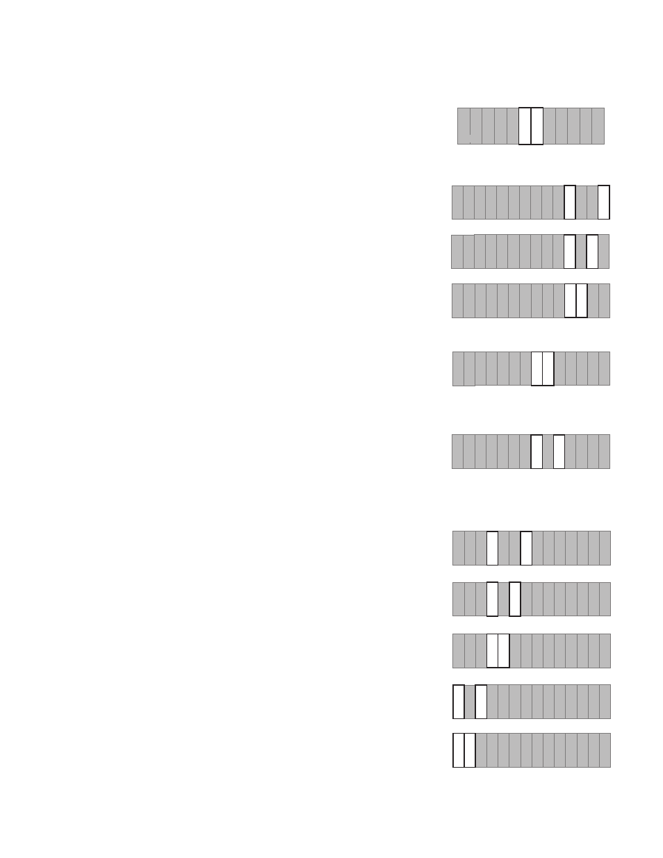
Sensor and Unpowered Input Connections
Do not apply power to these terminals as this will damage the control.
Outdoor Sensor
Connect the two wires from the Outdoor Sensor 070 to the terminals
Com Sen — Out
Sen (16 and 19). The Outdoor Sensor measures the outdoor air temperature.
Supply Sensor
Connect the two wires from the Supply Sensor 071 to terminals
Com Sen — Sup Sen
(16 and 18). The Supply Sensor measures the supply water temperature after mixing
has occurred.
Boiler Sensor
Connect the two wires from the Boiler Sensor 071 to terminals
Com Sen — Boil Sen
(16 and 17). The Boiler Sensor measures the supply water temperature from the boiler.
UnOccupied Switch
If an external timer or switch is used, connect the two wires from the external dry contact
switch to the
Com Sen —UnO Sw (13 and 14) terminals. When these terminals short
together, the control registers an UnOccupied signal.
Note If an external switch is closed between the terminals
Com Sen — UnO Sw (13
and 14), the 24 hr. Timer is disabled. Either the 24 hr. Timer or an external timer/
switch can be used, not both at the same time.
Zone Control Input
If an external Zone Control is used, connect the wire from the
Com Sen terminal on the
Zone Control to terminal
Com Sen (13) on the 371. Connect the wire from the Zo Out
terminal on the Zone Control to terminal
Zo In (15) on the 371.
Note The wires from the Zone Control are polarity sensitive. The system will not
operate if the wires are reversed.
Room Temperature Units (RTU) and Indoor Sensors
RTUs and / or Indoor Sensors provide indoor temperature feedback to the control.
DIP Switch set to
Zone 1 Heat andVar. Speed
• If zone 5 is used, connect an RTU or Indoor Sensor to the
Com Sen — RTU 5
(9 and 12) terminals on the control.
• If zone 4 is used, connect an RTU or Indoor Sensor to the
Com Sen — RTU 4
(9 and 11) terminals on the control.
• If zone 3 is used, connect an RTU or Indoor Sensor to the
Com Sen — RTU 3
(9 and 10) terminals on the control.
• If zone 2 is used, connect an RTU or Indoor Sensor to the
Com Sen — RTU 2
(6 and 8) terminals on the control.
• If zone 1 is used for heating, an RTU or Indoor Sensor must be connected to the
Com
Sen — RTU 1 (6 and 7) terminals on the control.
DIP Switch set to
Zone 1 Cool
• If the zone
1 relay is used to enable an external cooling control system, an RTU or
Indoor Sensor is not required for this zone.
• If the zone
1 relay is used to control a cooling unit, an RTU or Indoor Sensor must
be connected to the
Com Sen — RTU 1 (6 and 7) terminals on the control.
DIP switch set to
Floating
• An RTU or Indoor Sensor connected to terminals
Com Sen — RTU 5 (9 and 12) or
Com Sen — RTU 4 (9 and 11) does not operate a zone relay, but it will provide indoor
temperature feedback to the mixed supply.
• Other zones can use an RTU or Indoor Sensor as described above.
2
23
Setp
Dem
20 21
Com
1-2
24
25
27
Com
3-5
26
28
1
Cls
5
3
29
31
30
Opn
4
DHW
Dem
Boiler
22
DHW
Pmp
Com
Sen
UnO
Sw
RTU
2
9
RTU
3
6 7 8
RTU
4
RTU
1
Com
Sen
10 11
13
Zo
In
12
14
Sup
Sen
Com
Sen
15
17
16
18
Boil
Sen
Out
Sen
19
RTU
5
Com
Sen
Com
Sen
UnO
Sw
RTU
2
9
RTU
3
6 7 8
RTU
4
RTU
1
Com
Sen
10 11
13
Zo
In
12
14
Sup
Sen
Com
Sen
15
17
16
18
Boil
Sen
Out
Sen
19
RTU
5
Com
Sen
Com
Sen
UnO
Sw
RTU
2
9
RTU
3
6 7 8
RTU
4
RTU
1
Com
Sen
10 11
13
Zo
In
12
14
Sup
Sen
Com
Sen
15
17
16
18
Boil
Sen
Out
Sen
19
RTU
5
Com
Sen
Com
Sen
UnO
Sw
RTU
2
9
RTU
3
6 7 8
RTU
4
RTU
1
Com
Sen
10 11
13
Zo
In
12
14
Sup
Sen
Com
Sen
15
17
16
18
Boil
Sen
Out
Sen
19
RTU
5
Com
Sen
Com
Sen
UnO
Sw
RTU
2
9
RTU
3
6 7 8
RTU
4
RTU
1
Com
Sen
10 11
13
Zo
In
12
14
Sup
Sen
Com
Sen
15
17
16
18
Boil
Sen
Out
Sen
19
RTU
5
Com
Sen
Com
Sen
UnO
Sw
RTU
2
9
RTU
3
6 7 8
RTU
4
RTU
1
Com
Sen
10 11
13
Zo
In
12
14
Sup
Sen
Com
Sen
15
17
16
18
Boil
Sen
Out
Sen
19
RTU
5
Com
Sen
Com
Sen
UnO
Sw
RTU
2
9
RTU
3
6 7 8
RTU
4
RTU
1
Com
Sen
10
11
13
Zo
In
12
14
Sup
Sen
Com
Sen
15
17
16
18
Boil
Sen
Out
Sen
19
RTU
5
Com
Sen
Com
Sen
UnO
Sw
RTU
2
9
RTU
3
6 7 8
RTU
4
RTU
1
Com
Sen
10
11
13
Zo
In
12
14
Sup
Sen
Com
Sen
15
17
16
18
Boil
Sen
Out
Sen
19
RTU
5
Com
Sen
Com
Sen
UnO
Sw
RTU
2
9
RTU
3
6
7
8
RTU
4
RTU
1
Com
Sen
10 11
13
Zo
In
12
14
Sup
Sen
Com
Sen
15
17
16
18
Boil
Sen
Out
Sen
19
RTU
5
Com
Sen
Com
Sen
UnO
Sw
RTU
2
9
RTU
3
6 7
8
RTU
4
RTU
1
Com
Sen
10 11
13
Zo
In
12
14
Sup
Sen
Com
Sen
15
17
16
18
Boil
Sen
Out
Sen
19
RTU
5
Com
Sen