Step five — testing the wiring, Terminals 1 – 2, Terminals 2 – 3 – tekmar 274 Boiler Control User Manual
Page 23
23
of
44
©
2012 274_D
-
11/12
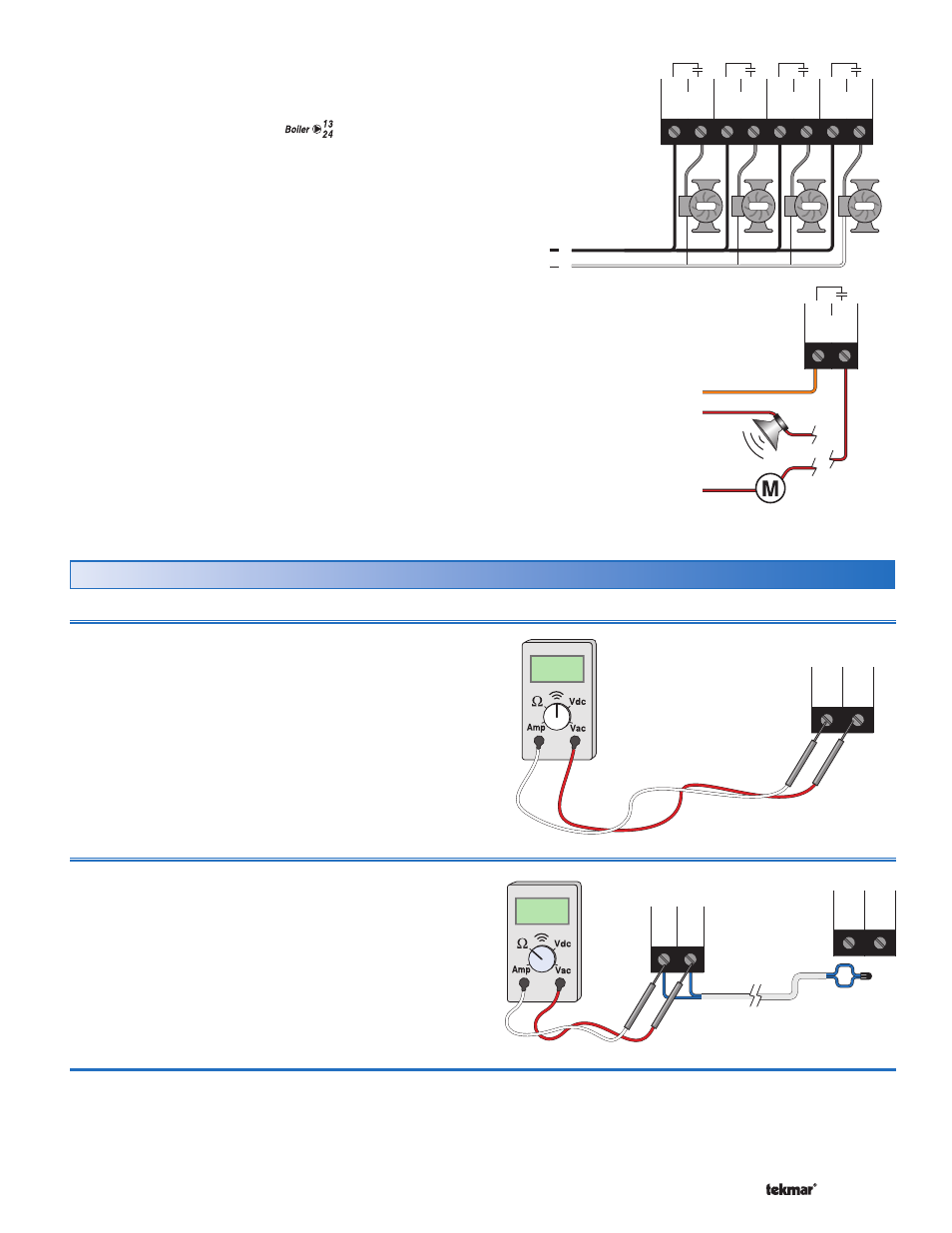
Wiring the Boiler Pumps
(RELAY TYPE = Boiler pump
)
Terminals 7-8, 9-10, 11-12 and 13-14 are dry contacts. No
power is available from these terminals. These contacts
can be used to turn on individual boiler pumps. Wire line
voltage to one side of the relay. The other side of the relay
goes to one side of the boiler pump and the remaining side
of the boiler pump goes to neutral.
Combustion Air / Alert Contact (C.A./Alert)
Terminals 15 and 16 are an isolated output in the control.
There is no power available on these terminals from the
control. These terminals are to be used as a switch to either
make or break power to the combustion air damper or alert
device. Since this is an isolated contact, it may switch a
voltage between 24 V (ac) and 230 V (ac).
N
L
Pump
Pump
Pump
Pump
4
3
2
1
Relay
Relay
Relay
Relay
14
13
12
11
10
9
8
7
Boiler
Pumps
120 V (ac)
OR
24 to 230 V (ac)
Alert
C.A./
16
15
Alert
Combustion
Air
L or R
N or C
N or C
tN4
Device
Com
tN4
+
-
Out
Com
3
2
Step Five — Testing the Wiring
General
The following tests are to be performed using standard
testing practices and procedures and should only be carried
out by properly trained and experienced persons.
A good quality electrical test meter, capable of reading from
at least 0-300 V (ac), 0-30 V (dc), 0-2,000,000 Ohms, and
testing for continuity is essential to properly test the wiring
and sensors.
Testing tN4 Network
Terminals 1 – 2
To test the tN4 Network, check the wires for continuity.
1. Disconnect the two wires (tN4 and Com) at one end and
connect them together.
2. Go to the other end of the wires and disconnect them.
3. Using an electrical test meter, check for continuity.
Ω
###
-
Com
tN4
2
1
Boiler
Control
274
Testing the EMS Output
Terminals 2 – 3
If an Energy Management System is used, measure the
voltage (dc) between the Com – and the Out + terminals (2
and 3). When the EMS calls for heat, a voltage between
0 – 10 V (dc) or 2 – 10 V (dc) should be measured at the
terminals.