Terminals 17 - 26, Terminals 7 – 22 – tekmar 274 Boiler Control User Manual
Page 22
©
2012 274_D
-
11/12
22
of
44
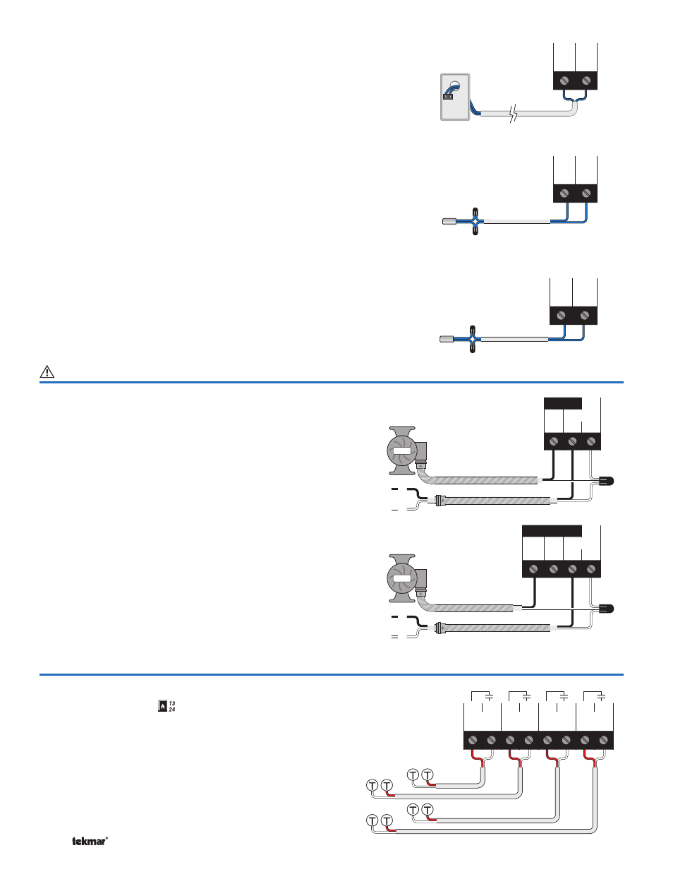
Outdoor Sensor (tekmar 070)
Connect the two wires from the Outdoor Sensor 070
to the Com and Out (2 and 3) terminals. The outdoor
sensor is used by the control to measure the outdoor air
temperature.
Note: If an Outdoor Sensor 070 is connected to a
tekmarNet
®
4 thermostat in the system, it is not required
to be connected to the control.
Boiler Supply Sensor (tekmar 082)
Connect the two wires from the Boiler Supply Sensor 082
to the Com and Boil (5 and 4) terminals. The Boiler Supply
Sensor is used by the control to measure the boiler supply
water temperature.
DHW or Boiler Return Sensor (tekmar 082)
Connect the two wires from the DHW Sensor 082 to the
Com and BRet / DHW (5 and 6) terminals. The DHW
Sensor is used by the control to measure the DHW water
temperature or the DHW Exchange Supply Temperature.
OR
Connect the two wires from the Boiler Return Sensor 082
to the Com and BRet / DHW (5 and 6) terminals. The Boiler
Return Sensor is used by the control to measure the boiler
return temperature.
+
-
Out
Com
3
2
Outdoor
Sensor
070
DHW Sensor 082
OR
Boiler Return Sensor 082
DHW
BRet/
Com
6
5
Sup
Com
Boil
5
4
Boiler Supply Sensor 082
Powered Output Connections
Terminals 17 - 26
Primary Pump P1
The Prim P1 output on terminal (18) is a powered output.
When the relay in the control closes, 115 V (ac) is provided
to the Prim P1 terminal (18) from the Power L terminal (19).
To operate the primary pump P1, connect one side of the
primary pump circuit to terminal (18) and the second side
of the pump circuit to the neutral (Power N) side of the 115
V (ac) power supply.
Primary Pump P2
The DHW / P2 output on terminal (17) is a powered output.
When the relay in the control closes, 115 V (ac) is provided
to the DHW / P2 terminal (17) from the Power L terminal
(19). To operate the primary pump P2, connect one side
of the primary pump circuit to terminal (17) and the second
side of the pump circuit to the neutral (Power N) side of the
115 V (ac) power supply.
N
L
Pump
Pump
L & N
18 19
20
Prim Power
P1
L
N
Primary
Pump
N
L
Pump
Pump
L & N
17
18 19
20
DHWPrim Power
P2
P1
L
N
Backup
Primary
Pump
OR
DHW
Pump
Non-Powered Output Connections
Terminals 7 – 22
Wiring the T-T
(RELAY TYPE = Boiler
)
Terminals 7-8, 9-10, 11-12 and 13-14 are dry contacts. No
power is available from these terminals. These contacts
can be used to either make or break power to a boiler or
boiler pump. The boiler must be wired to power as per the
manufacturers’ directions.
These terminals are typically connected to the boiler’s
control circuit (commonly labeled as T-T). Connect these
terminals directly to the boiler T-T connections.
4
3
2
1
Relay
Relay
Relay
Relay
14
13
12
11
10
9
8
7