tekmar 260 Boiler Control User Manual
Page 8
Copyright © D 260 -
03/09
8 of 20
FIRE DELAY (FIRE DELAY)
The Fire Delay is the delay time that occurs between the time that the 260 closes the
Boiler contact and the burner fires. This delay is
usually the result of burner pre-purge, or other forms of time delay built into the burner’s safety circuits.
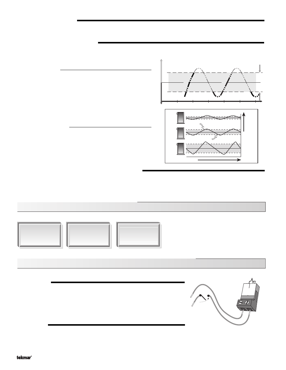
BOILER DIFFERENTIAL (BOIL DIFF)
An on / off heat source such as a boiler, must be operated with a differential in order to prevent short cycling. With the 260, either a
fixed or an auto differential may be selected.
Fixed Differential
The boiler differential is divided around the BOIL TARGET temperature.
The contact will close when the supply water temperature is 1/2 of
the differential setting below the BOIL TARGET temperature, and will
open when the supply water temperature is 1/2 of the differential setting
above the BOIL TARGET temperature.
Auto Differential (Ad)
If the Auto Differential is selected, the 260 automatically determines
the best differential as the load changes. This setting is recommended
as it reduces potential short cycling during light loads.
WARM WEATHER SHUT DOWN (WWSD) OCC & UNOCC
When the outdoor air temperature rises above the WWSD setting, the 260 turns on the WWSD segment in the display. When the
control is in Warm Weather Shut Down, the
Boiler Demand pointer is displayed, if there is a demand. However, the control does not
operate the heating system to satisfy this demand. The control does respond to a DHW demand and operates as described in
section C.
Section C: Domestic Hot Water (DHW)
Section C1
General Domestic
Hot Water (DHW)
Operation
Section C2
DHW Priority
Section C3
DHW with Low
Temperature
Boiler
Section C1: General Domestic Hot Water (DHW) Operation
DHW DEMAND
A DHW demand is required in order for the 260 to provide heat to the DHW system. The
260 registers a DHW demand when a voltage between 24 and 240 V (ac) is applied
across the
DHW Demand terminals (3 and 4). A DHW aquastat or setpoint control is used
as a switch in the DHW demand circuit. Once the 260 detects a DHW demand, the
DHW
Demand pointer turns on in the LCD and the control operates as described below.
DHW DEVICE
Once the 260 receives a DHW demand, the sequence of operation depends on the type of
DHW device selected. The DHW device is selected using the
DHW Valve / DHW Pump
DIP switch.
Supply W
ater
T
emperature
Time
Differential = 10
°F (5°C)
165
°F(74°C)
B
o
ile
r
o
ff
B
o
ile
r
o
n
155
°F (68°C)
160
°F (71°C)
B
o
ile
r
o
ff
B
o
ile
r
o
n
3
4
DHW
Demand
24 to 240 V (ac)
Aquastat
Off
On
Time
Heating Load
Differential