tekmar 260 Boiler Control User Manual
Page 5
Copyright © D 260 -
03/09
5 of 20
Section B: Boiler Reset
Section B1: General
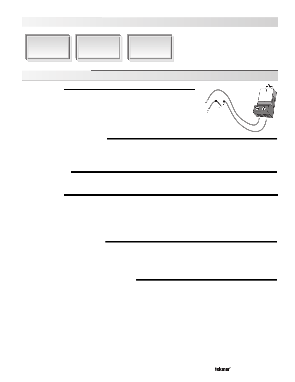
BOILER DEMAND
A boiler demand is required in order for the 260 to provide heat to the heating system. A
boiler demand is generated by applying a voltage between 24 and 240 V (ac) across the
Boiler Demand terminals (1 and 2). Once voltage is applied, the Boiler Demand pointer is
displayed in the LCD. If the 260 is not in WWSD, the 260 closes the
Boil P1 contact. The
260 calculates a BOIL TARGET supply temperature based on the outdoor air temperature
and settings. The 260 then fires the boiler, if required, to maintain the target supply
temperature.
BOILER PUMP OPERATION (
Boil P1)
The boiler pump contact (
Boil P1, terminal 7) closes whenever there is a boiler demand and the 260 is not in WWSD. The boiler pump
segment is displayed in the LCD. After the boiler demand has been satisfied, the 260 continues to operate the boiler pump for 20
seconds. This allows some residual heat to be purged out to the heating system. During WWSD, the boiler pump is operated based
on the exercise function. For boiler pump contact operation during DHW operation, refer to section C.
BOILER OPERATION
When the 260 determines that boiler operation is required, the
Boiler contact (11 and 12) closes. While the Boiler contact is closed, the
burner segment in the LCD is displayed.
INDOOR SENSOR
The indoor sensor is connected to the
Com and Indr terminals (17 and 18). In addition, power must be applied to the Boiler Demand
terminals (1 and 2) as described in the BOILER DEMAND section. With the indoor sensor connected, the 260 is able to sense the
actual room temperature. Indoor temperature feedback fine-tunes the supply water temperature in the heating system to maintain
room temperature. To adjust the room temperature, use the ROOM OCC or ROOM UNOCC setting in the ADJUST menu at the control.
If a multiple zone system is used with an indoor sensor, proper placement of the indoor sensor is essential. The indoor sensor should
be located in an area which best represents the average air temperature of the zones.
CHARACTERIZED HEATING CURVE
The 260 varies the supply water temperature based on the outdoor air temperature. The control takes into account the type of terminal
unit that the system is using. Since different types of terminal units transfer heat to a space using different proportions of radiation,
convection and conduction, the supply water temperature must be controlled differently. Once the control is told what type of terminal
unit is used, the control varies the supply water temperature according to the type of terminal unit. This improves the control of the air
temperature in the building.
BOILER TARGET TEMPERATURE (BOIL TARGET)
The BOIL TARGET temperature is determined from the
Characterized Heating Curve settings, outdoor air temperature, and optionally,
indoor air temperature. The control displays the temperature that it is currently trying to maintain as the boiler supply temperature. If
the control does not presently have a requirement for heat, it does not show a boiler target temperature. Instead, “- - -” is displayed in
the LCD.
Section B1
General
Section B2
Installer
Section B3
Advanced
1
2
Boiler
Demand
24 to 240 V (ac)