tekmar 260 Boiler Control User Manual
Page 11
Copyright © D 260 -
03/09
11 of 20
STEP THREE
ROUGH-IN WIRING
All electrical wiring terminates in the control base wiring chamber. The base has standard 7/8” (22 mm) knockouts which accept
common wiring hardware and conduit fittings. Before removing the knockouts, check the wiring diagram and select those sections of
the chamber with common voltages. Do not allow the wiring to cross between sections, as the wires will interfere with safety dividers
which should be installed at a later time.
Power must not be applied to any of the wires during the rough-in wiring stage.
• Install the Outdoor Sensor 070 and Boiler Sensor 0
82 according to the instructions in the Data Brochure D 070, and run the wiring
back to the control.
• If an Indoor Sensor 076 or 077 is used, install the indoor sensor according to the instructions in the Data Brochure D 074, and run
the wiring back to the control.
• Run wire from other system components (pumps, valve, boiler, etc.) to the control.
• Run wires from the 120 V (ac) power to the control. Use a clean power source to ensure proper operation. Multi-strand 16 AWG
wire is recommended for all 120 V (ac) wiring due to its superior flexibility and ease of installation into the terminals.
STEP FOUR
ELECTRICAL CONNECTIONS TO THE CONTROL
The installer should test to confirm that no voltage is present at any of the wires. Push the control into the base and slide it down until
it snaps firmly into place.
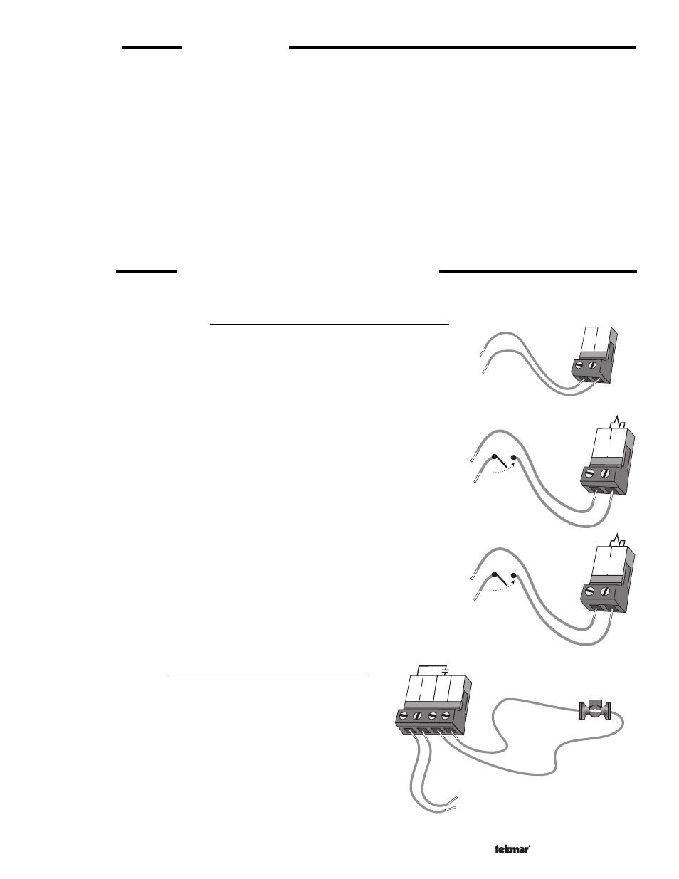
Powered Input Connections
120 V (ac) Power
Connect the 120 V (ac) power supply to the
Power L and Power N terminals (5 and 6).
This connection provides power to the microprocessor and display of the control. As
well, this connection provides power to the
Boil P1 terminal (7) from the Power L
terminal (5).
Boiler Demand
To generate a boiler demand, a voltage between 24 V (ac) and 240 V (ac) must be
applied across the
Boiler Demand terminals (1 and 2).
DHW Demand
To generate a DHW demand, a voltage between 24 V (ac) and 240 V (ac) must be
applied across the
DHW Demand terminals (3 and 4).
Output Connections
Boiler Pump Contact (
Boil P1)
The boiler pump output terminal (7) on the 260 is a powered output.
When the relay contact in the 260 closes, 120 V (ac) Line (L) is
provided to the
Boil P1 terminal (7) from the Power L terminal (5).
To operate the boiler pump, connect one side of the boiler pump
circuit to terminal 7, and the second side of the pump circuit to the
neutral (
N) terminal 8.
3
4
DHW
Demand
24 to 240 V (ac)
1
2
Boiler
Demand
24 to 240 V (ac)
5
6
120 V (ac)
L
N
Power
5
6
Power
Boil
P1
7
8
120 V (ac)
L
N
L
N
N
Boiler
pump