tekmar 260 Boiler Control User Manual
Page 13
Copyright © D 260 -
03/09
13 of 20
Test The Sensors
In order to test the sensors, the actual temperature at each sensor
location must be measured. A good quality digital thermometer with a
surface temperature probe is recommended for ease of use and
accuracy. Where a digital thermometer is not available, a spare sensor
can be strapped alongside the one to be tested, and the readings
compared. Test the sensors according to the instructions in the Data
Brochure D 070.
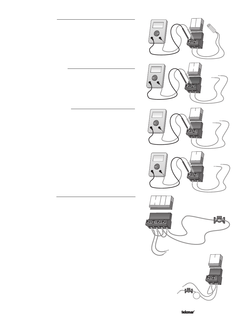
Test The Power Supply
Make sure exposed wires and bare terminals are not in contact with
other wires or grounded surfaces. Turn on the power and measure
the voltage between the
Power L and Power N terminals (5 and 6)
using an AC voltmeter. The reading should be between 108 and 132
V (ac).
Test The Powered Inputs
Boiler Demand
Measure the voltage between the
Boiler Demand terminals (1 and
2). When the boiler demand device calls for heat, you should
measure between 20 and 260 V (ac) at the terminals. When the
boiler demand device is off, you should measure less than 5 V (ac).
DHW Demand
If a DHW demand is used, measure the voltage between the
DHW
Demand terminals (3 and 4). When the DHW demand device calls
for heat, you should measure between 20 and 260 V (ac) at the
terminals. When the DHW demand device is off, you should measure
less than 5 V (ac).
Test The Outputs
Boiler Pump (
Boil P1)
If the boiler pump is connected to the
Boil P1 terminal (7) and N
terminal (8), make sure power to the terminal block is off, and install
a jumper between the
Power L and the Boil P1 terminals (5 and 7).
Install a second jumper between
Power N and N terminals (6 and
8). When power is applied to the
Power L and Power N terminals (5
and 6), the boiler pump should start. If the pump does not turn on,
check the wiring between terminal block and pump, and refer to
any installation or troubleshooting information supplied with the
pump. If the pump operates properly, disconnect the power and
remove the jumpers.
DHW Pump or Valve (
DHW Pmp / Vlv)
If a DHW pump or DHW valve is connected to the
DHW Pmp / Vlv terminals (9 and
10), make sure power to the pump or valve circuit is off and install a jumper between
those terminals. When the DHW circuit is powered up, the DHW pump should turn on
or the DHW valve should open completely. If the DHW pump or valve fails to operate,
check the wiring between the terminals and the pump or valve, and refer to any
installation or troubleshooting information supplied with these devices. If the DHW
pump or valve operates properly, disconnect the power and remove the jumper.
Ω
V
V
5
6
L
N
Power
108 to 132 V (ac)
Ω
V
V
1
2
Boiler
Demand
20 to 260 V (ac)
Ω
V
V
3
4
DHW
Demand
20 to 260 V (ac)
9
10
DHW
Pmp/Vlv
24 to 240 V (ac)
M
or
120 V (ac)
N
L
L
N
5
6
Power
Boil
P1
7
8
N
Boiler
pump
Ω
V
14 15
Com Boil
Ω