Powers 470 Series VisuGuard Pressure-Balancing Tempering Valve with LCD Temperature Display User Manual
Page 2
II473
Page 2
© November 2001 Powers
USA Phone: 800.669.5430 • Fax: 847.229.0526
Canadian office: Phone: 888.208.8927 • Fax: 888.882.1979
www.powerscontrols.com
CAUTION: Resetting of the spline stop can result in
higher temperatures. The mixer senses inlet pressure
changes only, so any variation in the inlet temperatures
will affect the control point and the desired maximum
temperature setting.
8. Verify that the stem dimension as shown in figure 2.
9. Locate, install, and tighten the trim plate with mixer
stem passing through it.
10. Apply adhesive stem gasket to trim plate with mixer
passing through it.
11. Locate and install the lever handle and its set screw
(handle should be pointing down when turned fully
clockwise). The set screw should then be tightened into
the stem groove as shown in figure 2.
MIXING PLATE ROTATION
1. Remove the four bonnet screws.
2. Remove bonnet and rotate valve stem 1/2 turn.
3. Reinstall bonnet with four bonnet screws.
BALANCE CHAMBER REMOVAL
1. Remove the four bonnet screws and the bonnet.
2. Remove the balance chamber carefully with pliers or
the cartridge puller p/n 401-202 (see figure 3).
3. Replace the cartridge and bonnet after finishing solder-
ing. Use silicone grease to lubricate cartridge O-rings
prior to reinsertion.
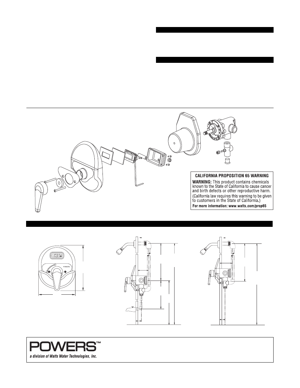
Front View
Tub and Shower Installation
Shower Only Installation
DIMENSIONAL DATA (millimeters [inches])
6
[152]
7-1/2
[191]
12
[305]
1-9/16 [40]
to
1-15/16 [50]
42
[1068]
Wall
36
[915]
3-1/8
[79]
78 [1981]
approx. to
finished floor
1/2 NPT
male inlet
1-7/8 [48] to 2-5/8 [67] with stem extension
Wall
30
[761]
3-1/8
[79]
78 [1981]
approx. to
finished floor
1/2 NPT
male inlet
1-9/16 [40]
to
1-15/16 [50]
1-7/8 [48] to 2-5/8 [67] with stem extension
All dotted line piping supplied by others.
Celcon is a registered trademark of Hoechst
Celanese Corporation.
Figure 4: Exploded View
Form
II473 0218
EDP# 6512219
Printed in U.S.A.