Installation cont – Powers PB410 Series Pressure Balancing Mixing Valves - Pressure Balancing Mixing Valve User Manual
Page 3
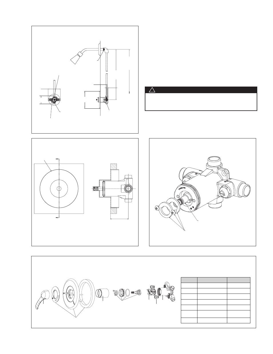
Installation Cont.
n
Item No.
Description
Kit No.
1
Handle Kit
420 049
2
Trim Plate Kit
410 022
3
Sleeve Kit
220 054
4
Bonnet/Stem Kit
410 410
5
Cartridge
900 240
6
Check stop
Replacement Kit
900 050
7
Body
N/A
3
78" (1981mm)
Approx. to
Finished Floor
1
⁄
2
"
(13mm)
24" (609mm)
Approx.
Tub outlet TP be plugged.
Plug by others.
7" (178mm)
2
7
⁄
16
" (62mm) MAX.
1
7
⁄
16
" (37mm) MIN.
1
⁄
2
" - 14 NPT
Male Inlet
'Tub' to be on
the bottom
1
⁄
2
" IPS Connections or
1
⁄
2
" Copper Sweat
Connection
5"
(127mm)
3
1
⁄
4
" (83mm)
4
5
⁄
8
"
(117mm)
Rough - In Guide
Exploded view chart.
Figure 6
Figure 4
Figure 5
MIN - MAX
1
7
⁄
16
- 2
7
⁄
16
(37 - 62mm)
G
G
4
5
⁄
8
(117cm)
High Temp
Limit Stop
Stem
12. The high-temperature limit stop is located at the center of
the bonnet. To adjust the temperature, unscrew two bon-
net screws halfway. To increase the temperature, rotate
the stem counter-clockwise to the required temperature
using the handle for leverage. Do not place pliers or chan-
nel locks on the spline of the stem. Tighten the two bonnet
screws. To decrease temperature, turn the stem clockwise
to the required temperature. Rotate the limit stop with the
help of small flathead screwdriver clockwise until it touch-
es the stem stop. Tighten the two bonnet screws. Close
valve and open it to verify setting (See Figure 5).
1
3
4
5
7
6
Figure 3 - Rough-in Dimensions - Shower ONLY
Always verify the maximum temperature setting of the valve
when any changes are made. This should also be checked
as a part of a facilities maintenance/safety program.
WARNING
!