Powers SH1434 Triple Valve User Manual
Technical instructions
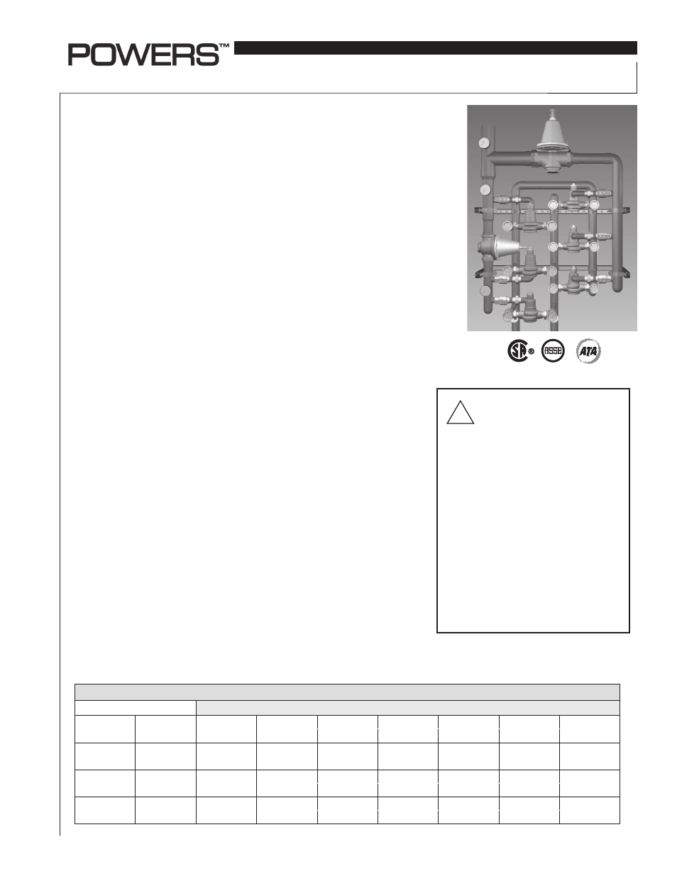
Description
n
Table 1 Capacity
n
HydroGuard
®
XP SH1434 & LFSH1434 Triple,
Quad & Six Valve Hi/Lo Supply Fixture
Technical Instructions
IS-P-SF-SH1434-TV_QV_6V
Advanced Thermal Activation
Powers' HydroGuard
®
XP Series SH1434 & LFSH1434 Triple, Quad and Six Valve
Hi/Lo's are fully assembled, factory tested systems, designed to provide safe
water throughout commercial and institutional facilities. Each consists of MM434
or LFMM434 and SH1434 or LFSH1434 Master Tempering Valves which utilize par-
affin-based actuation technology to sense and adjust outlet temperature. Each
system includes a PRV, ball valves, pressure/temperature gauges and Powers'
triple-duty check stops and are supported by heavy-duty welded struts. Optional
equipment includes cabinets and/or Powers' AquaSentry
®
2 high-temperature
alarm system. (Not available with LFSH1434 Series).
Maximum Operating Pressure ............................. 125psi (861 kPa)
Maximum Hot Water Temperature ...................... 200°F (93°C)
Minimum Hot Water Supply Temp* .................... 5°F (3°C) Above Set Point
Hot Water Inlet Temperature Range ................... 120 -180°F (49 - 82°C)
Cold Water Inlet Temperature Range ................. 40 - 80°F (4 - 27°C)
Minimum Flow** ...................................................... 0.5 gpm (1.89 lpm)
Temp. Adjustment Range *** ............................... 90 - 160°F (32 - 71°C)
Listing/Compliance (Valve Only)............................ ASSE 1017, CSA B125
*With Equal Pressure
**Minimum flow when Hi/Lo valve is installed at or near hot water source recirculating tempered
water with a properly sized continuously operating recirculating pump.
***Note: Low limit cannot be less than the cold water temperature. For best operation, hot
water should be at least 5°F (3°C) above desired set point.
Specifications
n
Operation
n
The Triple, Quad and Six Valves Hi/Lo feature one low capacity valve that works in
parallel with multiple high capacity valves. During low demand, the low capacity
valve handles the load requirements. As the load demand increases, the pres-
sure reducing valve, which is set at a certain pressure differential, will open and
allow flow through the high capacity valves to assist the low capacity valve in
meeting the increased load requirements.
Flow Capacity at 50-50 Mixed Ratio
P r e s s u r e D r o p A c r o s s V a l v e
Model
Min. Flow
C
V
5psi
10psi
20psi
30psi
45psi
60psi
to ASSE 1017
(34 kPa)
(69 kPa)
(138 kPa)
(207 kPa)
(310 kPa)
(414 kPa)
SH1434TV and
LFSH1434TV
1 gpm
62.0
139 gpm
196 gpm
277 gpm
340 gpm
416 gpm
480 gpm
4 lpm
526 lpm
742 lpm
1049 lpm
1287 lpm
1575 lpm
1817 lpm
SH1434QV and
LFSH1434QV
1 gpm
83.3
186 gpm
263 gpm
373 gpm
456 gpm
559 gpm
645 gpm
4 lpm
704 lpm
996 lpm
1412 lpm
1726 lpm
2116 lpm
2442 lpm
SH1434-6V and
LFSH1434-6V
1 gpm
126.3
282 gpm
400 gpm
565 gpm
692 gpm
847 gpm
978 gpm
4 lpm
1067 lpm
1514 lpm
2139 lpm
2620 lpm
3206 lpm
3702 lpm
WARNING: TO ENSURE THE
ACCURATE AND RELIABLE
OPERATION OF THIS PRODUCT, IT IS
ESSENTIAL TO:
• Properly size each valve based on the indi-
vidual application.
• Properly design the recirculation system to
minimize pressure and temperature variations.
• Conduct an annual maintenance program to
ensure proper operation of all critical com-
ponents.
THIS VALVE MUST BE USED IN
CONJUNCTION WITH TEMPERATURE
ACTUATED POINT-OF-USE DEVICES THAT
COMPLY WITH ASSE 1016, 1069, OR 1070.
FAILURE TO COMPLY WITH PROPER
INSTALLATION INSTRUCTIONS COULD
CONTRIBUTE TO VALVE FAILURE, RESULTING
IN IN JURY OR DEATH.
!