Troubleshooting, Repair kit, Warranty – Powers LM490/LM490-10 Series Thermostatic Tempering Valves for Hot Water Heater & Multiple Lavatory Installations User Manual
Page 2: Installation instructions
LFLM490 is factory pre-set to 120°F (49°C) and LFLM490-10 is
factory set to 90°F (31°C) outlet temperatures under the following
conditions:
Cold inlet: 60° - 70°F (16 - 21°C)
Hot inlet: 140° - 145°F (60 -
63°C) Supply Pressures: 45psi
(310 kPa)
1. Let the water flow for at least
two minutes to allow supply
temperature to stabilize.
2. Place a thermometer in the
outlet water stream.
3. Loosen handle screw with hex
wrench.
4. Handle must be lifted 1/4" to adjust temperature. Rotate
handle clockwise to decrease temperature and counter-
clockwise to increase the temperature.
5. Lower handle and tighten screw.
6. Check for outlet temperature.
NOTICE
Pressure differential between hot & cold water supplies must be
less then 25%.
Fluctuating or erratic hot water temperature at fixture:
Unbalanced Pressure. Install balancing or throttling valve at the
hot and cold water supplies and adjust accordingly for demand.
Hot water backing up into cold water line:
Hot water pressure is higher than cold water pressure.
Examine check valves for dirt & debris, clean as necessary.
Cannot adjust water temperature to desired temperature:
Install balancing or throttling valve at the hot and cold water
supplies and adjust accordingly for demand.
High pressure drop through the tempering valve:
Valve undersized. Install larger thermostatic tempering valve.
Insufficient hot water during peak demand:
Check flow requirement during peak demand period. Use larger
thermostatic tempering valve.
Troubleshooting
n
Repair Kit
n
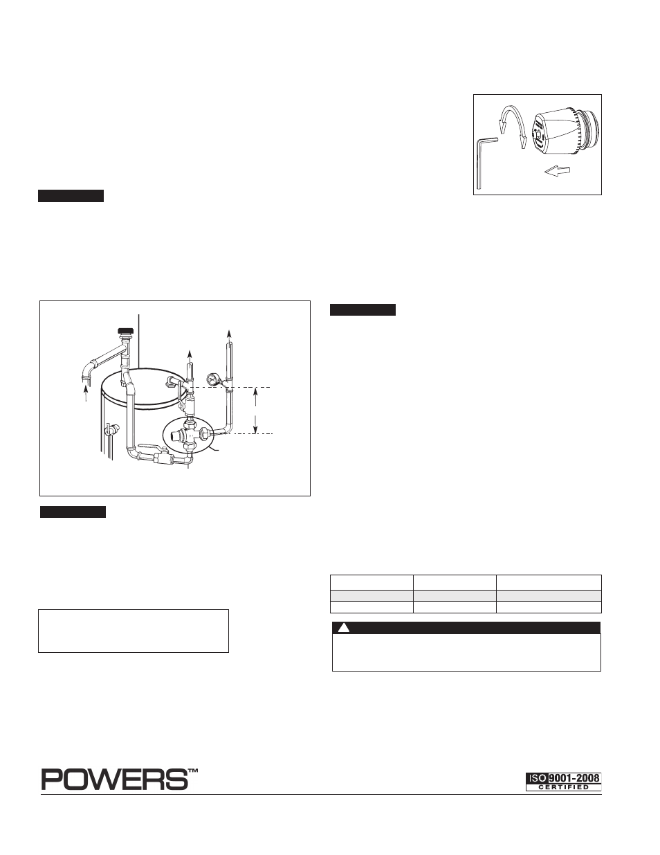
To Adjust Temperature (Figure 2)
n
Model
Part #
Description
LFLM490
490-090
Plunger/Motor Assembly
LFLM490-10
490-190
Plunger/Motor Assembly
USA: Tel: (800) 669-5430 • Fax: (847) 229-0526 • www.powerscontrols.com
Canada: Tel: (888) 208-8927 • Fax: (888) 479-2887 • www.powerscontrols.ca
IS-P-LM490-LM490-10 1336
EDP# 6511207
© 2013 Powers
Warranty
n
The Seller warrants that the equipment manufactured by it and covered by this order or contract is free from defects in material and workmanship and, without
charge, equipment found to be defective in material or workmanship will be repaired, or at Seller’s option replaced F.O.B. original point of shipment, if written
notice of failure is received by Seller within one (1) year after date of shipment (unless specifically noted elsewhere), provided said equipment has been properly
installed, operated in accordance with the Seller’s instructions, and provided such defects are not due to abuse or decomposition by chemical or galvanic action.
ThiS expreSS warranTy iS in lieu OF and excludeS all OTher warranTieS, guaranTeeS, Or repreSenTaTiOnS, expreSS OF implied. There are
nO implied warranTieS OF merchanTaBiliTy Or OF FiTneSS FOr a parTicular purpOSe. The Seller assumes no responsibility for repairs made on the
Seller’s equipment unless done by the Seller’s authorized personnel, or by written authority from the Seller. The Seller makes no guarantee with respect to material
not manufactured by it.
A Watts Water Technologies Company
WARNING: This product contains chemicals known to the
State of California to cause cancer and birth defects or
other reproductive harm.
For more information: www.watts.com/prop65
V acuum Relief V alve
Temperatur
e Gauge
Cold
Cold
LFLM490, LFLM490-10
8" - 10"
T emper
ed
Hot
Hot to Appliances
T&P
Relief Valve
H
C
M
Cold
Figure 1. Domestic Hot Water Application
NOTICE
To prolong the life of the series LFLM490 or LFLM490-10 valves,
it is recommended that the hot water inlet to the valve should be
8-10”(200-305mm) below the hot water inlets.
Flush all pipes thoroughly before installation. Installation and
field adjustment are the responsibility of the installer.
1. Close both hot and cold water shutoff valves upstream of the
tempering valve.
2. Bleed pressure from the system.
3. Route copper tubing or piping to fit valve dimensions.
4. For valves with Quick-Connect tailpieces refer to "Quick-
Connect Installation" instructions.
5. Remove tailpieces from the valve and make sure union nuts
are over the tubing/piping before connecting to the tailpiece.
NOTICE
If soldering, remove unions and gaskets from valve body prior to
soldering to prevent damage to valve from excessive heat.
6. Flush piping again, install valve using filter gasket on hot and
cold water inlets and fiber gasket on mixed water outlet.
7. Turn on the cold and hot water. If a leak is observed, tighten
connections as necessary to stop leak before proceeding.
Installation Instructions
n
Turn
Hotter
Hex Wrench
Colder
Unscrew, Lift Cap
to Adjust
Figure 2.
Temperature Adjustment
For valves with CPVC or PEX end connections, do not exceed the
tubing manufacturers pressure and temperature ratings. Refer to the
tubing manufacturers product specifications for that information.
WARNING
!