Powers e700 Series Combination T/P Tempering Valves - Upgrade from Biltmore 900 User Manual
Installation instructions
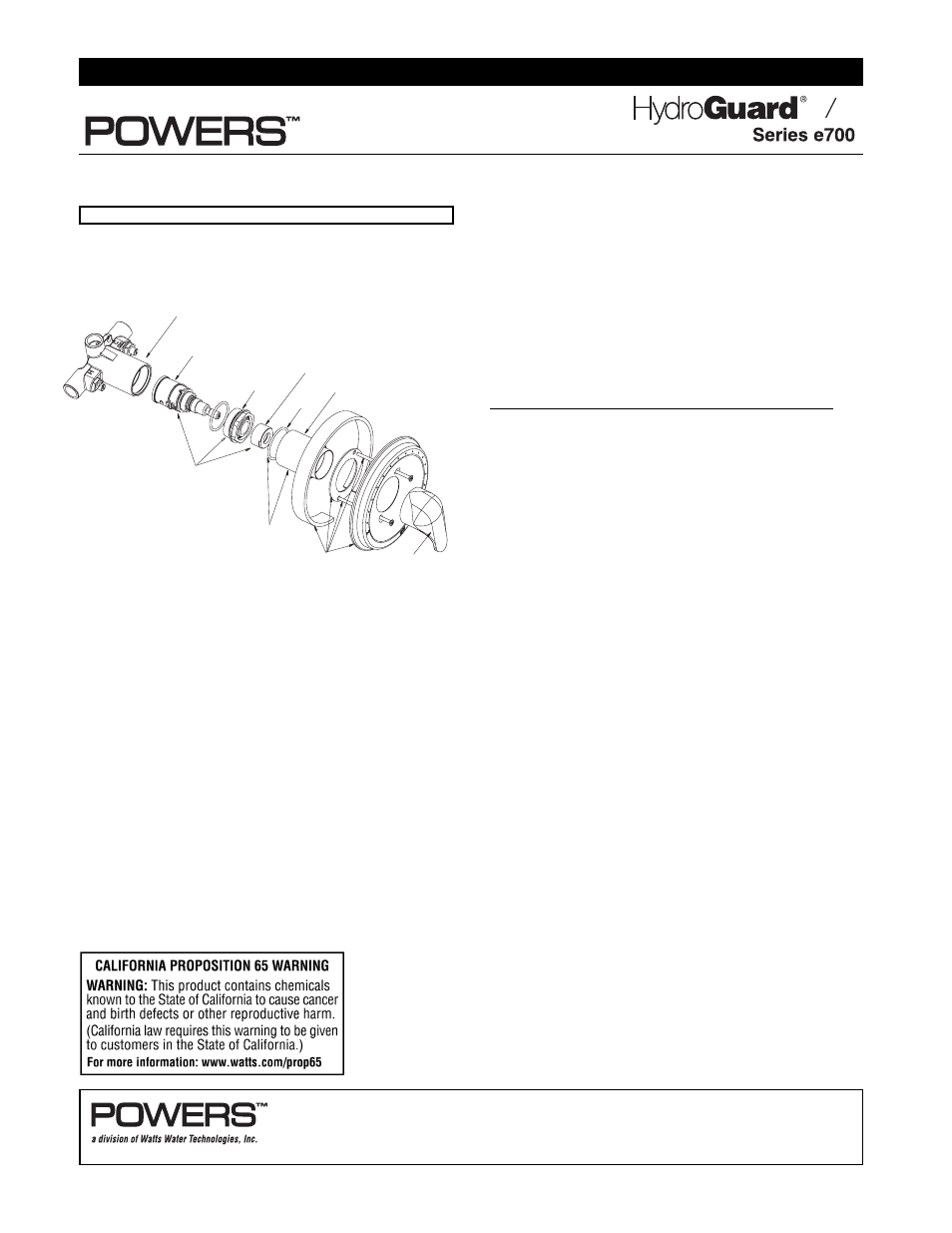
e700 RETROFIT INSTRUCTIONS
The following instructions explain how to retrofit your existing
Biltmore 900 Model 3 to an e700 which meets ASSE 1016 T/P
and CSA B125 T/P requirements. See the exploded view of
this new assembly bellow:
Before you begin your upgrade, take the time to ensure you
have all the necessary pieces. Your retrofit kit, for each valve,
consists of the following (refer to above diagram when taking
inventory):
1. Cartridge Kit
4. Handle Kit
2. Lubricant
5. Sleeve Kit
3. Trim Kit
After you verify that you have everything needed to complete
the retrofit, proceed with the next section.
Retrofit:
Follow the instructions below to perform your retrofit. Save all
components until you have successfully completed your
retrofit.
Disassembly:
1. Turn off hot & cold water supply-stops.
2. Remove the handle and trim plate.
3. Remove bonnet.
4. Remove all internal components from valve body.
5. At this point you should have an empty valve body.
You are now ready to put the new components into your
existing valve.
Reassembly:
1. Ensure the inside of the valve body is free of deposits
and debris. Clean as necessary.
2. Place the cartridge into the body ensuring following:
a) "C" on the cartridge should be on the cold inlet side.
b) Align tab on the bottom of the cartridge to the groove
in the body.
3. While holding cartridge firmly, screw bonnet into body;
tighten to 100 + 20/-0 in-lbs.
4. Turn the hot and cold water supplies back on and verify
there is no leakage.
Maximum Temperature Setting/Handle Rotation Stop
The handle rotation setting must be adjusted to limit the
distance the user can rotate the handle towards the full hot
water position.
CAUTION: Any repair or modification of the valve may affect
the high temperature setting. The maximum temperature
setting must be checked by the installer before use.
5.Adjust the valve to the desired maximum outlet tempera-
ture [110°F (43°C) max]. Screw on the high temp. limit stop
until it touches the stem shoulder.
6. Turn the stem clockwise until the water stops. Open valve
to full hot position and verify max outlet temperature setting.
6 (a) For 220 453:
1. Attach indicator plate gasket to the back of the trim
plate making sure horizontal holes on the gasket
matches horizontal holes on the trim plate. Indicator
plate locator hole matches diagonal hole on the trim
plate. Peel off backing of trim gasket and attach to the
inside top edge of the trim plate. Gasket should
approx. be 1/16" beyond the plate edge.
2. Install the trim plate with the screws provided.
3. Snap on the indicator plate. Guide on the back of the
plate goes into the locator hole.
4. Install sleeve O-ring on the bonnet. Slide sleeve on the
bonnet.
CAUTION: Indicator plate must be installed before sleeve.
5. Install handle and tighten the setscrew.
6 (b) For 220 451 & 220 452
1. Place sleeve O-ring on the bonnet shoulder. Slide
sleeve over the O-ring until it stops.
2. Install trim plate gasket.
3. Install trim plate with the screw provided.
4. Install handle and tighten set screw.
7. Your retrofit is complete!
You have just converted your type “P” valve to type “T/P”
If you have any problems, comments, or suggestions, please
contact your local Powers representative. We are interested
in feedback from the field. You can find them at www.power-
scontrols.com.
HANDLE
KIT
TRIM
KIT
CARTRIDGE
KIT
BODY
SLEEVE
KIT
CARTRIDGE
B0NNET
TEMP. LIMIT STOP
SLEEVE
"O" RING
SLEEVE
Figure 1
IIe700R 0617
EDP# 6511199
INSTALLATION INSTRUCTIONS
Complete Upgrade – Kit #220-451 & 220-452, 220-453
T P
© 2006 Powers
USA: Phone: 1.800.669.5430 • Fax 1.847. 229 . 0526 • www.powerscontrols.com
Canada: Phone: 1.888.208.8927 • Fax 1. 888. 882 .1979 • www.powerscontrols.ca
IIe700R