Powers e420 Series Combination T/P Tempering Valves - Cartridge & Trim Upgrade User Manual
Page 2
6. Place the wax element into the stem assembly, small end
first, and place this bonnet-stem-motor assembly into/onto
the valve body. Rotate the bonnet assembly to line up the
bonnet screw holes and reinstall and tighten the four
bonnet screws.
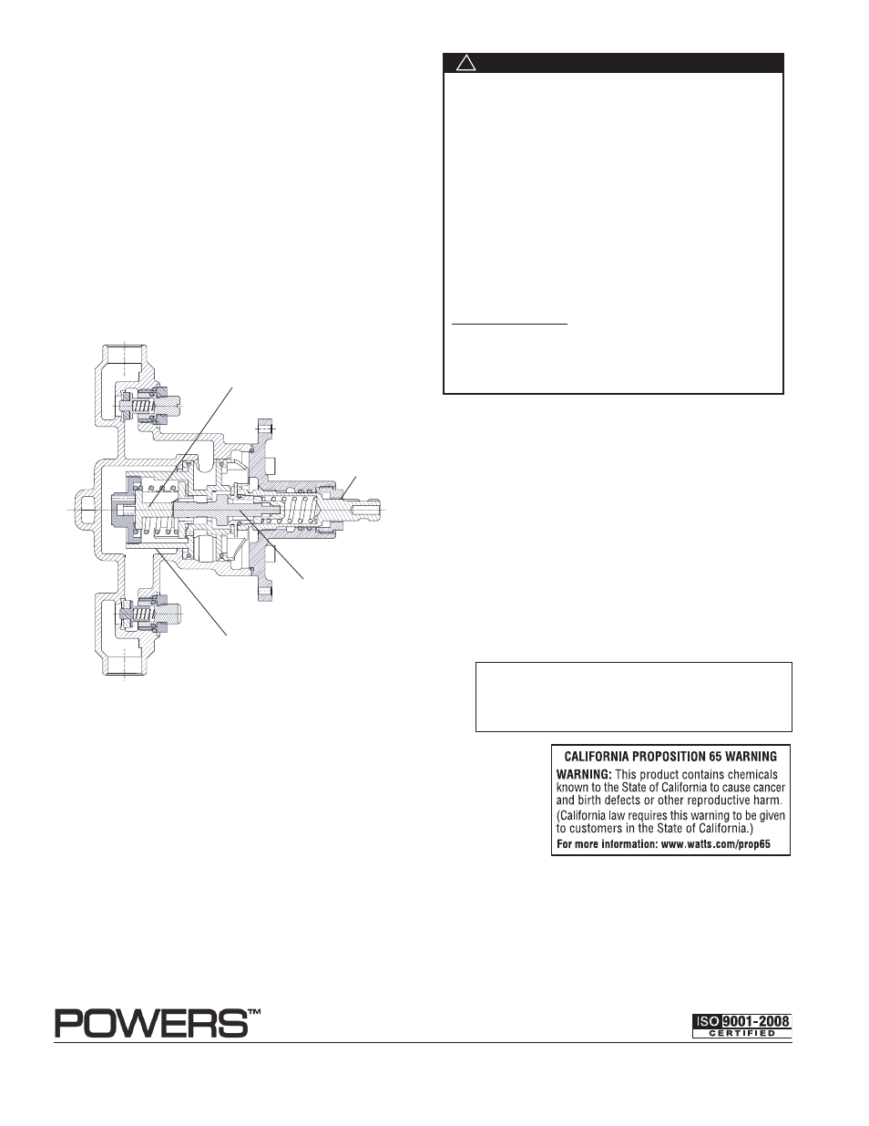
See cutaway below to see how everything goes together.
(Figure 3)
7. Rotate the stem assembly clockwise, by hand, until it
bottoms out on the cartridge. At this point your valve is
in the off position.
8. Turn the hot and cold water supplies back on and verify there
is no leakage. If the valve leaks disassemble and
go back to step #1 and reassemble.
9. Maximum Temperature Setting
Maximum temperature setting adjustment (Figure 3) must be set
on the job. The high temperature limit stop is threaded into the
bonnet and is turned counter clockwise for a decreased set-
ting. Powers recommends a maximum setting of 105°F (41°C).
To adjust temperature, rotate handle to the maximum desired
outlet temperature, screw temperature limit stop until it touches
stem’s shoulder. Close valve and open it to verify setting.
10. Your valve should now be set properly. Verify proper
operation by rotating the stem from the off position,
counterclockwise, to the high temperature position.
Verify the temperature does not exceed your desired
maximum temperature. Rotate stem back to the
off position.
11. Peel off backing of dial gasket and attach it to the inside top
edge of dial plate. Make sure gasket is approximately
1/16" beyond the plate edge.
12. Hold plate firmly against the wall. Thread sleeve on the
bonnet making sure that the cut away on the sleeve is
facing out and is in the bottom position when tightened.
Do not use any tool which will scratch the sleeve surface.
13. Install handle with the screw provided on to the stem and
tighten in place. Ensure the set screw lines up with the
groove on the adjustment stem.
Figure 3
Shuttle
Hot Water Supply
Cold Water Supply
Adjustment
Stem
Advanced Thermal
Actuator
Cartridge Assembly
Warranty
n
The Seller warrants that the equipment manufactured by it and covered by this order or contract is free from defects in material and workmanship and, without
charge, equipment found to be defective in material or workmanship will be repaired, or at Seller’s option replaced F.O.B. original point of shipment, if written
notice of failure is received by Seller within one (1) year after date of shipment (unless specifically noted elsewhere), provided said equipment has been properly
installed, operated in accordance with the Seller’s instructions, and provided such defects are not due to abuse or decomposition by chemical or galvanic action.
ThiS expreSS warranTy iS in lieu OF and excludeS all OTher warranTieS, guaranTeeS, Or repreSenTaTiOnS, expreSS OF implied. There are
nO implied warranTieS OF merchanTaBiliTy Or OF FiTneSS FOr a parTicular purpOSe. The Seller assumes no responsibility for repairs made on the
Seller’s equipment unless done by the Seller’s authorized personnel, or by written authority from the Seller. The Seller makes no guarantee with respect to material
not manufactured by it.
USA: Phone: 1.800.669.5430 • Fax 1.847. 229.0526 • www.powerscontrols.com
Canada: Phone: 1.888.208.8927 • Fax 1.888.479.2887 • www.powerscontrols.ca
IS-P-e420R 1045
EDP#6512298
© 2010 Powers
A Watts Water Technologies Company
ATTENTION INSTALLER: After installation, please leave this
Instruction Sheet for occupant’s information.
IMPORTANT: Inquire with governing authorities for local
installation requirements.
FAILURE TO COMPLY WITH PROPER INSTALLATION
AND MAINTENANCE INSTRUCTIONS COULD
CONTRIBUTE TO THE VALVE FAILURE, RESULTING IN
INJURY. TO ENSURE THE ACCURATE AND RELIABLE
OPERATION OF THIS PRODUCT, IT IS ESSENTIAL TO:
• properly size each valve based on the individual appli-
cation.
• properly design the recirculation system to minimize
pressure and temperature variations.
• conduct an annual maintenance program to ensure
proper operation of all critical components.
• check outlet temperature to ensure it does not exceed
105°F (41°c). make sure temperature limit stop is
properly re-set to maximum 105°F (41°c) following
valve maintenance or repair. Tampering with limit
stop in any way may result in scalding temperature
causing serious bodily harm.
Periodic Inspection: Corrosive water conditions, tem-
peratures over 210°F, unauthorized adjustments or
repair could render the valve ineffective for the service
intended. Regular checking and cleaning of the valve’s
internal components helps assure maximum life and
proper product function.
WARNING
!