Installation, Operation cont – Powers e420 Series Combination T/P Tempering Valves User Manual
Page 2
Installation
n
2
78" [1981]
APPROX.
TO FINISHED
FLOOR
1 7/16" [37] MIN.
2 7/16" [62] MAX.
7/8" [23]
WALL
Ø4" [102]
1/2" NPT
MALE INLET
'S' TO BE
ON TOP
6 1/8" [155]
5 5/8" [142]
3 1/8" [79]
R1 5/8" [R40]
1/2" NPTF
CONNECTIONS
4 1/8" [105]
ALL DOTTED LINE
PIPING SUPPLIED
BY OTHERS.
78" (1981mm)
Approx.
To Finished
Floor
"S" to Be
on Top
WALL
5 1/2"
(139mm)
15/16"
(23mm)
All Dotted Line Piping
Supplied By Others
6 1/16"
(155mm)
3 1/8"(79mm)
4 1/8"(105mm) 4"(101mm)
3 1/8"(79) max
2 3/8"(60) min
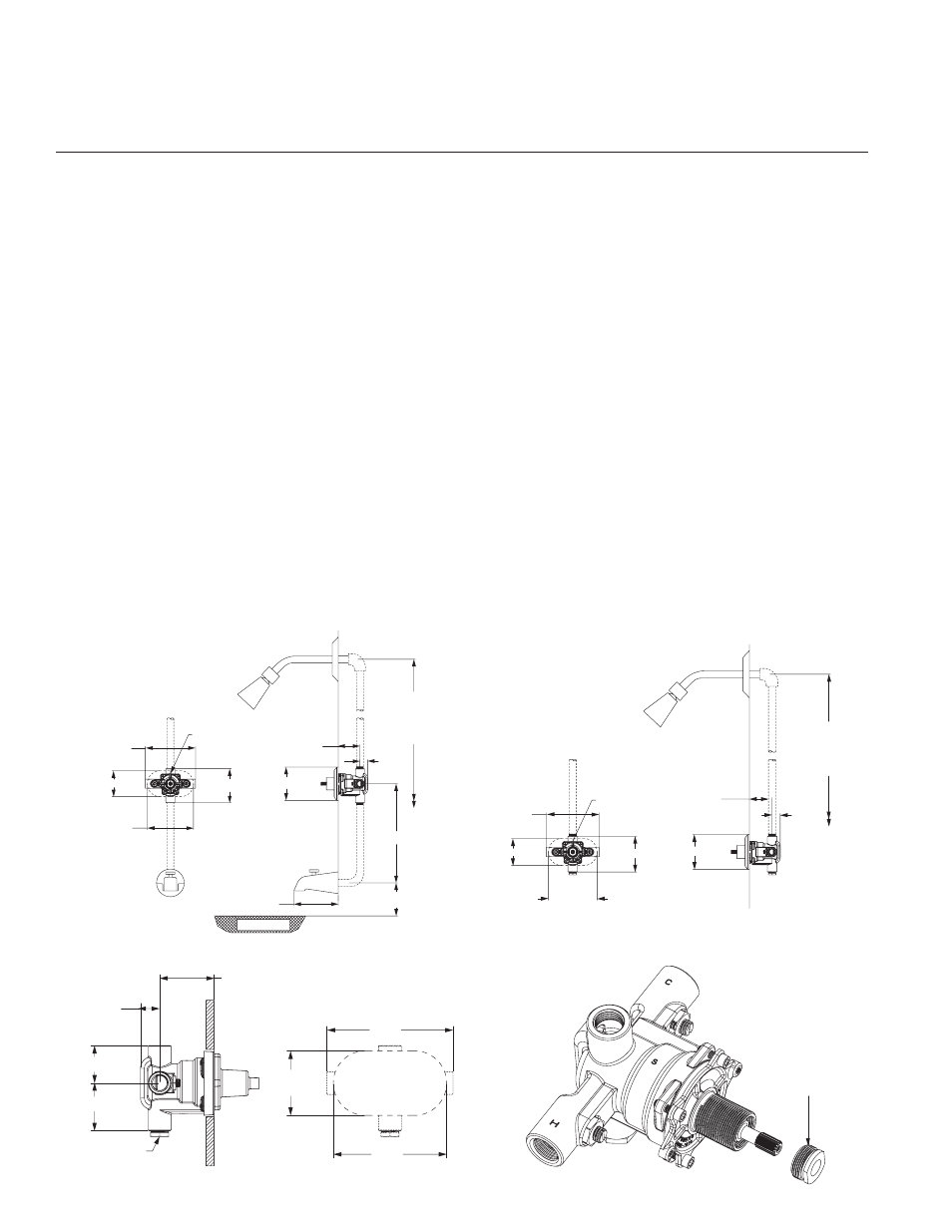
Figure 2:
Rough-in Dimensions
– Shower Only
Wall
78" (1981mm)
Approx.
To Finished
Floor
"S" to Be
on Top
6 1/16"
(155mm)
5 1/2"
(139mm)
5 3/8"(137mm)
4" (102mm) Approx
12" (305mm)
15/16"
(23mm)
Tub Rim
All Dotted Line Piping
Supplied By Others
3 1/8"(79mm)
4 1/8"(105mm)4"(101mm)
3 1/8"(79mm) max
2 3/8"(60mm) min
Figure 1:
Rough-in Dimensions
– Tub and Shower
3 1/8"(79mm) max
15/16"
(23mm)
6 1/16"
(155mm)
5 1/2"
(139mm)
3 1/8"
(79mm)
1 13/16"(46mm)
2 5/16"(58mm)
Optional For
3 Port Valve
2 3/8"(60mm) min
SIDE VIEW
FRONT VIEW
Figure 3:
Rough-in Guide
Clockwise for
cooler temperature.
Counter clockwise
for warmer temperature
Figure 4:
Max Temperature
Setting
NOTE: Installation should be in accordance with accepted plumbing
practices. Flush all piping thoroughly before installation. Failure to do
so can result in a valve malfunction.
TO INSTALL
1 . Position mixing valve 2 3/4" ±3/8" (69mm ± 10mm) from inlet center
to finished wall surface. For reference a rough-in guide is provided,
ensure it is pushed on fully and the valve is closed when positioning
valve. The tub outlet port is marked TUB” and should face down.
Facing the front of the mixing valve, connect hot water to left side
and connect cold water to right side. The mixing valve has “C” and
“H” cast into the body near the appropriate ports. Inlets and outlet
connections must be piped correctly for proper operation of valve.
If hot and cold water connections are reversed, valve will not func-
tion properly.
2. For tub and shower installations, see Figure 1. Pipe bottom outlet
port “TUB” directly to the diverter tub spout. The mixing valve is
designed to operate without the use of a twin ell. Pipe top outlet port
“S” to the showerhead.
3. For shower only installation, see Figure 2. Pipe top outlet port “S”
directly to the showerhead and plug bottom port.
CAUTION: When soldering during the installation process, do not
heat the valve any higher than the temperature required to flow solder.
Excessive overheating of the valve may cause damage to the valve
internals. By following this recommendation, you will be able to solder
the valve without removing either the cartridge or the checkstops inter-
nals. If either brazing or resistance (electric) solder is used, all check-
stop and valve internals must be removed.
4. Turn hot and cold water supplies on and verify there are no leaks.
5. Rough-in guide installation
a. Before strapping the pipes and before completing the finished
wall, slide rough-in guide onto the mixing valve stem and press
fit into place, see Figure 3. (valve stem must be rotated fully
clockwise).
b. The rough-in guide will insure the proper size opening and
location of the finish wall.
6. After finished wall is completed, remove rough-in guide to allow
installation of the trim.
7 . Peel off backing of dial gasket and attached it to the inside top edge
of dial plate. Make sure gasket is approximately 1/16" beyond the
plate edge.
8. Hold plate firmly against the wall. Thread sleeve on the bonnet mak-
ing sure that the cut away on the sleeve is towards you and is in
the bottom position when tightened. Do not use any tool to tighten
which will scratch the sleeve surface.
9. Install handle with the screw provided.
10. Maximum temperature setting adjustment (Figure 4) must be set on
the job. The high temperature limit stop is threaded into the bonnet
and is turned counter clockwise for an increased setting and clock-
wise for a decreased setting. Powers recommends a maximum
setting of 110°F (43°C). To adjust temperature, rotate handle to the
maximum desired outlet temperature, screw temperature limit stop
until it touches stem’s shoulder. Close valve and open it to verify
setting.
Operation cont.
n
to the outlet. If the hot or cold supply water temperature or pressure
changes, the thermal actuator will contract or expand. This movement
repositions the shuttle to maintain the desired temperature. With the
adjustment handle in full clockwise (OFF) position, the shutoff disc
closes the mixing chamber from the outlet.
A temperature limit stop limits the movement of the control handle. The
standard HydroGuard
®
e420 valve is factory set to deliver tempered
water up to 110°F [43°C] with equal supply pressures, with hot water
temperature 140°F [60°C], cold water temperature 60°F [15.6°C]