Powers 900X I/P Flowrite II Pressure Regulators User Manual
Page 3
3
Output:
Connect output to 1/4 NPT port marked "OUT" on base of unit.
The two unmarked 1/4 NPT ports may be used as alternate out-
put ports or for a gauge to measure output pressure. Unused
ports must be plugged.
Electrical Connections:
Connect electrical signal to leads exiting side of unit through 1/2
NPT conduit fitting. For direct acting (where increasing signal
increases output pressure), connect positive signal to black
lead and negative to white. For reverse acting (increasing signal
decreases output pressure), connect positive signal to white
lead and negative to black.
4. Set signal to high end of the signal scale. (For reverse acting,
set to low end of the signal scale).
5. Adjust "SPAN" screw until output pressure is set to the high
end of the output scale.
6. Repeat steps 2, 3, 4, and 5 until no further readjustment is
necessary.
7. Replace protective caps.
Transducer should be calibrated after mounting. If transducer is
calibrated in an upright position, then mounted at an angle, read-
justment of the "ZERO" is necessary.
1. Remove plastic cap from "ZERO" and "SPAN" adjustment
screw access holes.
2. Set signal to low end of the signal scale. (For reverse acting,
set to high end of the signal scale).
3. Adjust "ZERO" screw until output pressure is set to the low
end of the output scale. Turn counterclockwise to increase
pressure, clockwise to decrease pressure. If output pressure
does not change when screw is turned, turn screw counter-
clockwise until pressure starts to rise.
Calibration
n
Maintenance
n
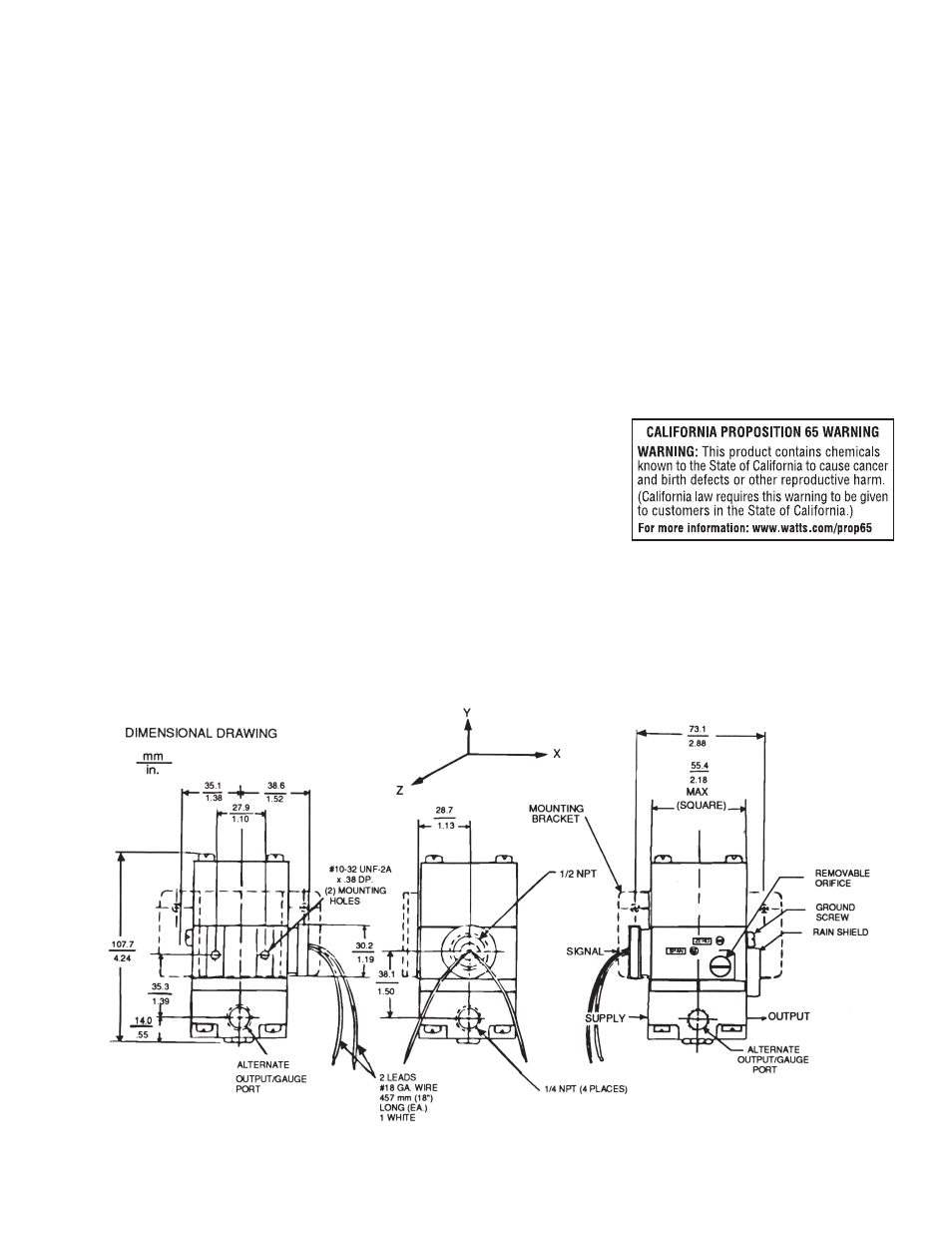
Figure 2
If internal clogging occurs due to improper filtering of the supply
air, the orifice can be cleaned without removing the unit from
its mounting or plumbing. Turn off the supply air. Unscrew and
remove the orifice assembly. Clean the orifice through the side
of the orifice assembly using a wire that has a smaller diameter
than 0.015 in. (0.38 mm). Shake out any loose particles inside of
the orifice assembly. Screw orifice assembly back into unit.