Warranty, Troubleshooting, Figure 3: stem position information power s – Powers 900 Series Biltmore Series Pressure Balancing Mixing Valves User Manual
Page 2: Figure 5
USA: Phone: 1.800.669.5430 • Fax 1.847. 229.0526 • www.powerscontrols.com
Canada: Phone: 1.888.208.8927 • Fax 1.888.479.2887 • www.powerscontrols.ca
IS-P-900 1041
EDP# 6512223
© 2010 Powers
A Watts Water Technologies Company
Warranty
n
The Seller warrants that the equipment manufactured by it and covered by this order or contract is free from defects in material and workmanship and, without
charge, equipment found to be defective in material or workmanship will be repaired, or at Seller’s option replaced F.O.B. original point of shipment, if written
notice of failure is received by Seller within one (1) year after date of shipment (unless specifically noted elsewhere), provided said equipment has been properly
installed, operated in accordance with the Seller’s instructions, and provided such defects are not due to abuse or decomposition by chemical or galvanic action.
ThiS expreSS warranTy iS in lieu OF and excludeS all OTher warranTieS, guaranTeeS, Or repreSenTaTiOnS, expreSS OF implied. There are
nO implied warranTieS OF merchanTaBiliTy Or OF FiTneSS FOr a parTicular purpOSe. The Seller assumes no responsibility for repairs made on the
Seller’s equipment unless done by the Seller’s authorized personnel, or by written authority from the Seller. The Seller makes no guarantee with respect to material
not manufactured by it.
DESCRIPTION
TROUBLESHOOTING
REPAIR KIT NO.
gaSKeT and diSc
1) water leaks at valve stem and/or bonnet.
900 030 models 1 and 2
replacemenT
2) water leaks at valve shutoff.
3) water leaks at checkstop.
900 028 model 3
inTernalS
1) with mixer handle in mid postition, hw flows with cw.
900031a, model 1
replacemenT
checkstop closed or cw flows with hw checkstop closed. 900 031 model 2
900 032 model 3
checKSTOp
1) checkstop will not completely shut off.
900 049 models 1 and 2
replacemenT
900 050 model 3
Troubleshooting
n
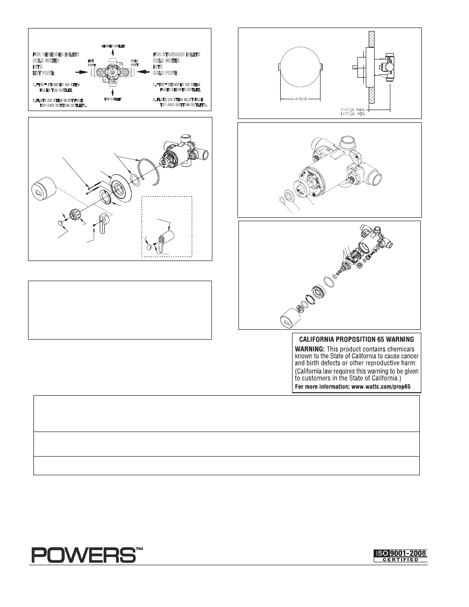
HOT
PORT
COLD
PORT
SHOWER OUTLET
TUB OUTLET
FOR STANDARD INLETS
COLD WATER
INTO
COLD PORT:
1. "TOP" STAMPED ON STEM
FACES SHOWER OUTLET.
2. FLATS ON STEM MUST FACE
TOP AND BOTTOM OUTLETS.
FOR REVERSED INLETS
COLD WATER
INTO
HOT PORT:
1. "TOP" STAMPED ON STEM
FACES TUB OUTLET.
2. FLATS ON STEM MUST FACE
TOP AND BOTTOM OUTLETS.
Figure 3: Stem Position Information
POWER
S
Dial Gaskets
ABS
Dial
Plate*
Dial Plate
Screws (2)
ABS Lever Handle
Kit #900 103
Metal Lever
Handle*
900 070
ABS Lever
Handle Screw
800 164
ABS Lever
Handle Button
900 096
ABS Lever
Handle
900 091
Acrylic
Handle*
900019C
Acrylic
Handle
Button
900 140
Acrylic
Handle Screw
800 168
Metal Lever
Handle Screw
800 164
900 094
080 026
900 093
(
not used in 905 valves)
900 090
*Round Stainless Steel Dial Plate
900020A
Graphic
Insert
900 095
Sleeve*
900 132
Figure 4
NOTE: For valves sold without checkstops, it is rec-
ommended that the valve be installed where there is
shutoff upstream of the valve, so that the valve may
be easily serviced and accessed. if this is not possible,
the valve should include a shutoff or combination
checkstop/shutoff on the inlets.
Silicone
Greas
e
NOTE: SweaT inlets
shown. Threaded
inlets also available.
* Use Sleeve 900 132 in Kit 900 268 with ABS Dial.
Use Sleeve 800015H in Kit 900 269 with Round Stainless Dial.
Figure 5
High Temperature Stop
Retainer
O-ring
Figure 6: Max. Temperature Setting/Handle Rotation
Stop
REPAIR KITS: For further
information on repair and
maintenance, see TI900.