Link distance, Antenna location, 4 link distance – BridgeWave AR80 User Manual
Page 9: 5 antenna location
AR/GE/FE/U 80/80X Installation Manual
4
58000519 rev. D
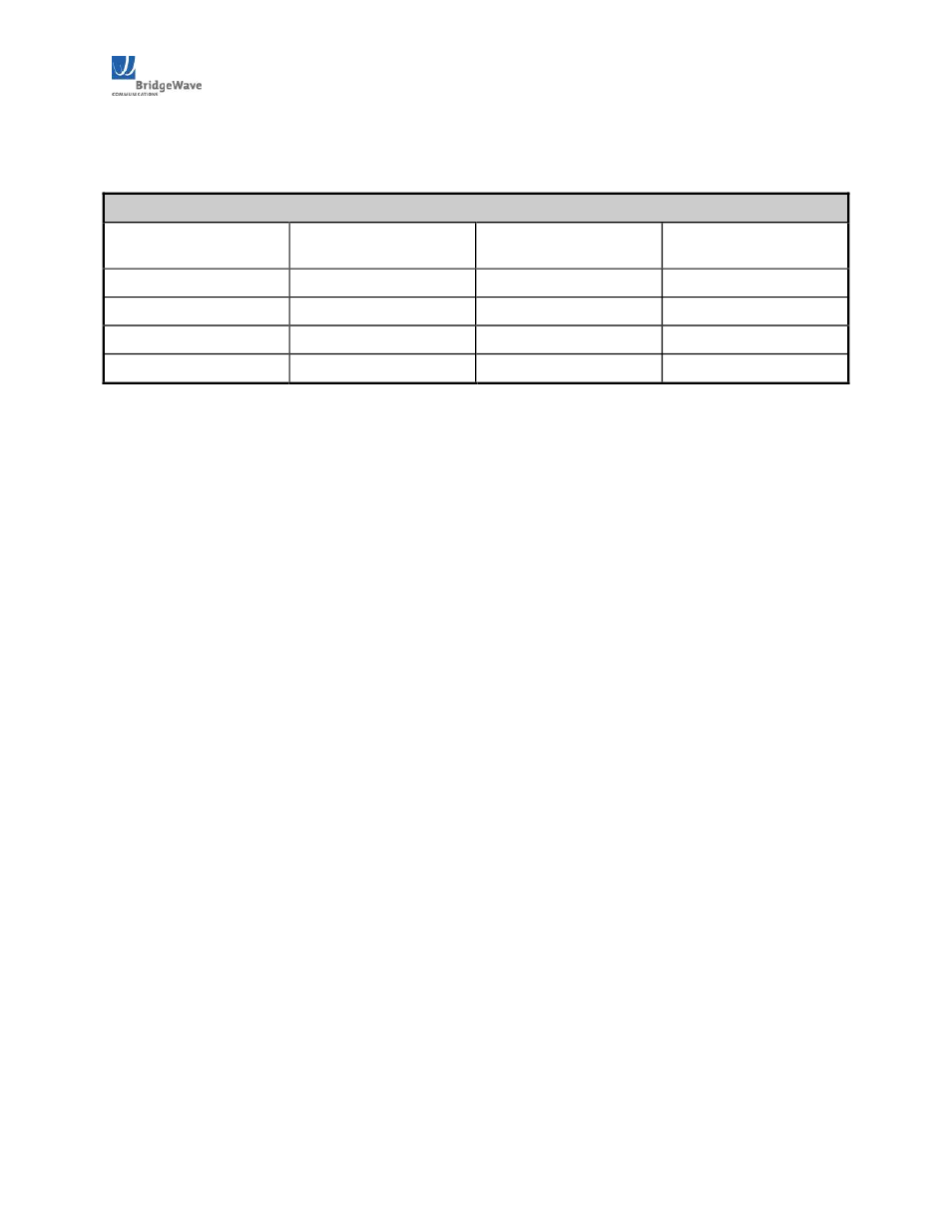
The following table details the minimum F1 (First Fresnel) clearance needed from obstacles in order
to ensure the radios will operate properly.
Table 2.31: Minimum Path Clearance
Path Length
(meters)
Minimum F1 Clearance
(meters)
Path Length
(miles)
Minimum F1 Clearance
(feet)
1000
0.58
0.62
1.9
2000
0.82
1.24
2.7
5000
1.3
3.10
4.3
10000
1.8
6.21
5.9
2.4 Link Distance
Measurement of the link distance is important in estimating the link availability and calculating
expected Receive Signal Level (RSL). This measurement can be performed using the Latitude and
Longitude coordinate readings from a Global Positioning System (GPS) device, which is placed near
the proposed locations of the antennas. Additionally GPS reading will be required in order to comply
with the FCC registration process.
The Minimum 80GHz Link distances are as follows:
· AR/GE/FE80: 328 feet (100 meters)
· AR/GE/FE80X: 1312 feet (400 meters)
To estimate maximum distances and availabilities for a given product and region, BridgeWave’s
Path Availability calculator can be used. To obtain the latest version of BridgeWave’s Path
Availability calculator, contact BridgeWave’s Customer Service or search eService Center
Knowledgebase.
2.5 Antenna Location
The optimum location for the antennas must be determined. The ideal location should provide for
ease of erecting and mounting the antenna, as well as providing unimpeded LOS to the remote
location. The following factors should be taken into account:
· Type of mounting—fixed or roofsafe pole mounting.
· Location of fiber and DC power wiring ingress/egress of the building.
· Length of cable runs.
· Confirmed Earth Grounding connection points.
· Obstructions, including allowances for tree growth.
· Accessibility of the radio mounting location.
· Accessibility of the site during and after working hours.