Cabling, 6 cabling – BridgeWave AR80 User Manual
Page 10
AR/GE/FE/U 80/80X Installation Manual
5
58000519 rev. D
2.6 Cabling
The installation site should be inspected to determine the run paths for the fiber cable and power
cable from the radio equipment to the termination point. Locations for roof penetration should be
identified. The routing and securing of all cables should conform to all applicable codes and
requirements. Depending on the likelihood of damage due to foot traffic or equipment movement,
cabling conduit may be required. The maximum cable run length as specified for the equipment
being installed must not be exceeded, refer to Table 2.61 and 2.62 for cable types and limitations.
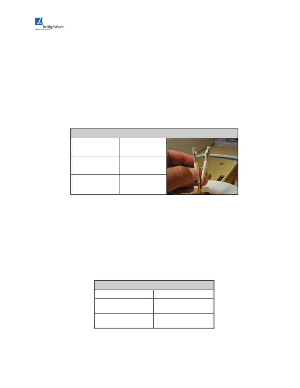
The radio requires LC type connectors on duplex multimode fibers to properly connect between the
radio and the users network equipment. Singlemode fiber connections are not supported for use
with the standard product. The network equipment end of the fibers should be terminated with
connectors that match the user’s network equipment fiber interface.
Table 2.61: Maximum Fiber Length
Fiber Cable Length
Cable Type
Up to 270 meters
62.5/125 μm
Up to 500 meters
50/125 μm
The 80GHz radio includes a 100240 VAC power adaptor, suitable for indoor operation only, that
converts the AC voltage from a standard electrical outlet in the wall to DC voltage. For outdoor
rated power supply options, contact BridgeWave customer service. The radio requires a minimum of
15.0 VDC at the connector on the radio unit (24.0 VDC maximum) to function properly.
When planning the cable run from the indoor AC power adaptor to the radio unit, it is required to use
the cable gauge (AWG) indicated below to ensure adequate voltage at the radio. The indoor and
outdoor portions of the DC power cabling must conform to all respective indoor and outdoor
national and local electrical and building codes; note that requirements may differ for the indoor and
outdoor portions of the cabling and that a grounded surge protector is normally required at the point
where the cable enters the building. The DC power cabling must consist of two 12 or 14 gauge
stranded conductors based on the required cable run length.
Table 2.62: Minimum DC Cable Size
DC Cable Length
Conductor Size
Up to 125 meters
14 AWG
(2.5mm²)
Up to 200 meters
12 AWG
(4mm²)
Figure 2.61 shows a standard 14gauge wire that has been fitted with the power connectors
(provided) for the radio’s internal power supply necessary to mate with the (not provided) DC power