BridgeWave AR80 User Manual
Page 32
AR/GE/FE/U 80/80X Installation Manual
27
58000519 rev. D
If you do not obtain a Quality voltage of 2VDC, do not proceed to
calibrate the system. Ensure you are aligned and achieve your
target RSL level. This can be confirmed for your path distance by
looking up the RSL voltage to distance curve in Appendix B.
4. At this point you need to connect the fiber cable (or a fiber loopback if no network gear is
terminated to the far end of the fiber).
If using a fiber loopback, remove immediately when the Link LED starts blinking.
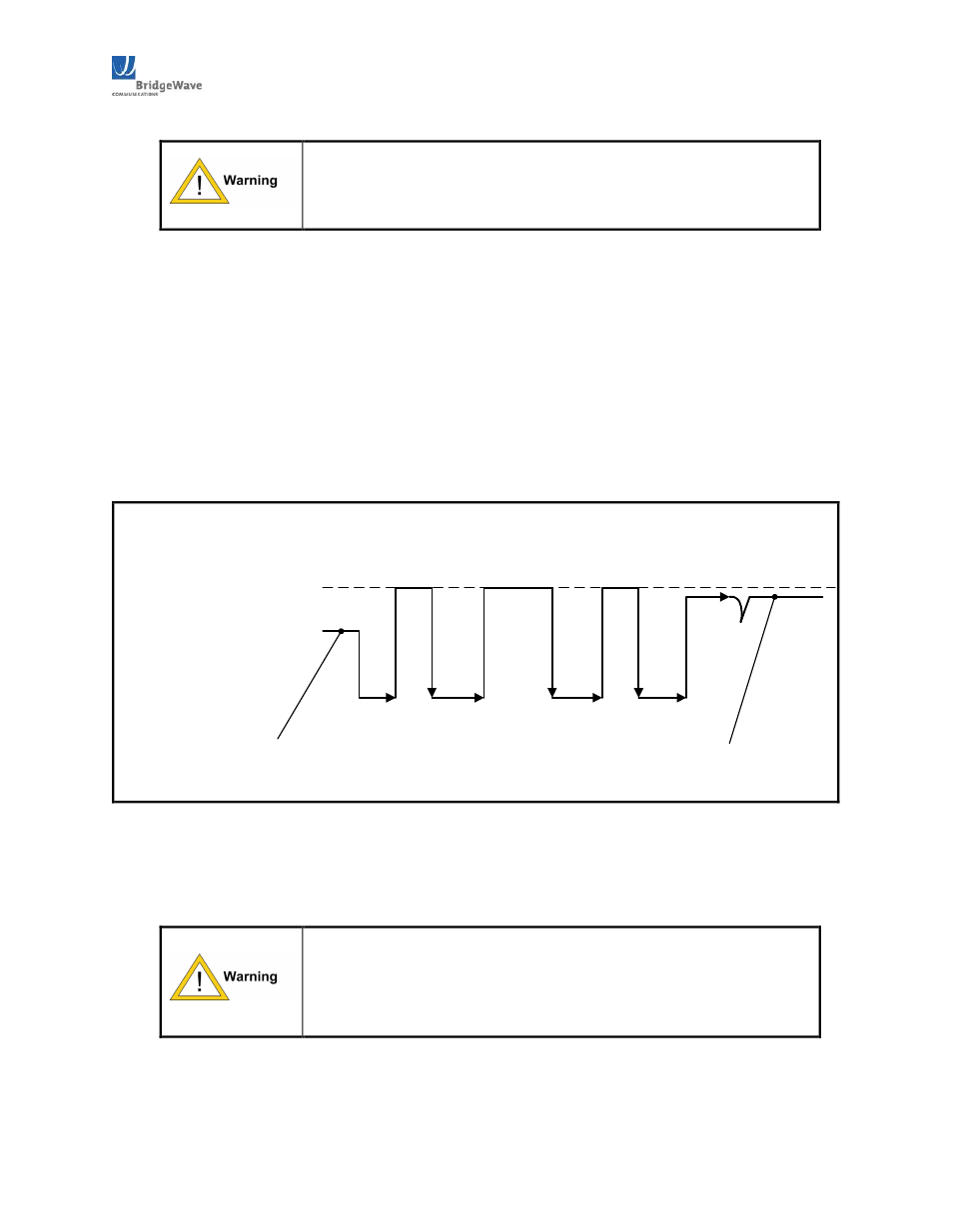
Calibrate one side at a time and while monitoring the Quality voltage with DVM. Verify you are
getting a 'quadruple hump'. i.e. voltage will rise, drop, rise, drop, and rise again, as illustrated below.
It should end with a 3.0VDC to 3.3VDC reading on your DVM. Also verify the radio ‘Link LED’ is
also ‘flashing’ on/off during this process. See Figure 3.10.11 for an illustration of the Quality
Voltage as it fluctuates during the calibration process.
Radio Link LED
stops flashing
2.0 3.3VDC
Cal
ibr
at
ing
1
00
0
M
bp
s
m
od
e
10 sec.
C
alib
ra
ting
1
00
M
bp
s
m
od
e
1V
2
V
3V
3
.3
V
Fiber connected, Radio Link
LED starts flashing
Quality Voltage during Calibration Process (90120 sec.)
Figure 3.10.11: Quality Voltage reading during Auto Calibration process
If you cannot obtain a good quality voltage and you have obtained the target RSL, contact Technical
Support at (408) 5676906 or email [email protected] for further assistance.
You must wait for the Auto Calibration process to complete on one
radio terminal before auto calibrating the remote radio and
ensure both radios pass the calibration process. Failure to wait
for the calibration to complete may result in a failure to create an
RF connection between radio terminals.