Qual & rsl test cable, 11 qual & rsl test cable – BridgeWave AR80 User Manual
Page 35
AR/GE/FE/U 80/80X Installation Manual
30
58000519 rev. D
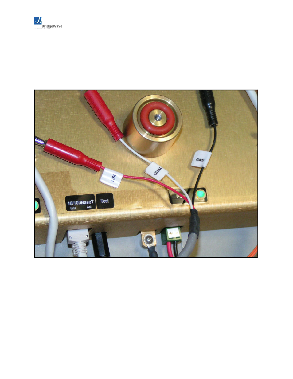
3.11 QUAL & RSL Test Cable
The alignment procedure is optimized through the use of the provided test cable. This test cable is
designed for use with a digital voltmeter (not provided) to read the Link Quality and Receive Signal
Level (RSL) voltage generated by the radio’s receiver. See Figure 3.111.
Figure 3.111:
Supplied test cable for measuring Link Quality and Receive Signal Level voltages
1. To read the RSL value of the radio, insert GND (ground) and RSL banana plugs into the
voltmeter. Note the RSL voltage. The voltage may be fluctuating; in this case, note the maximum
value seen.
2. To read the Link Quality value of the radio, insert GND (ground) and QUAL banana plugs into
the voltmeter. Note the Link Quality voltage. After the radios have performed an auto calibration
the quality voltage should read 3.03.3VDC if the link is aligned on the main antenna beam and
there are no obstructions (i.e., trees, buildings, etc…) in the path, the link distance is within the
operating parameters of the radio (see Section 2.4 above), and it is not raining heavily.