BridgeWave AR80 User Manual
Page 22
AR/GE/FE/U 80/80X Installation Manual
17
58000519 rev. D
A 48Volt DC version is available for this product. The power
connector is the same but the connector location is slightly moved.
The NMS ’Status Page’ reading will still read 24V.
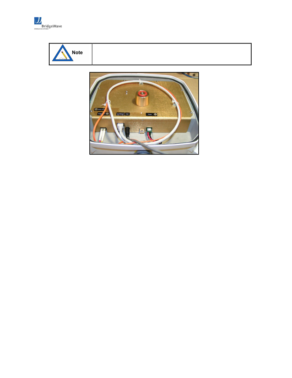
Figure 3.7.21: 80GHz power and data cables with
service loop for strain relief and proper fiber bend
radius.
3.7.3 Ground Cabling
The preferred method for grounding the radio unit is to ground the mast to a ground source, since
this provides the largest grounding surface contact possible. If this is not possible, then use the
following procedure:
1.
Attach the lug of the ground cable (not provided) with the radio to one of the two #8
holes at the bottom of the radio using a #832 x ½” long bolt, #8 lock washer and #8 flat
washers (not provided).
2.
Connect other end of the ground cable to a nearby ground location.
3.7.4 10/100BaseT Surge Suppressor
If the 10/100BaseT port is permanently connected to other network equipment (not normally
required), it should be connected using Cat5e UTP cables rated for the outdoor and/or indoor
environments where the cables will be run.
It is essential that the cabling be connected to the radio unit through an Ethernetrated surge
suppressor inside of the plastic back cover of the unit, and a surge suppressor should also be used at
the point where the cable enters a building or is connected to other outdoor equipment that does not
already contain surge suppression hardware.