Retract gear installation – E-flite Deuces Wild 25e2 ARF User Manual
Page 31
31
E-flite Deuces Wild Assembly Manual
Retract Gear Installation
Required Parts
Wing center section
Fuselage assembly
Nose gear retract
Main gear retract (right and left)
Brass pushrod connector (2)
Quick disconnect (male and female)
Nylon connector backplate (2) Air line
Steering cable
Cable crimp (4)
Cable fitting (2)
2mm x 8mm machine screw (2)
Air tank
Air fill fitting
Air line
T-fitting
3/16 inch wheel collars (4) (not included)
3mm x 8mm self-tapping countersink screw (12)
Required Tools and Adhesives
Hobby knife w/#11 blade
Covering iron
Pencil
Drill
Thin CA
Pin drill
Phillips screwdriver: #1, #2
Side cutters
Pliers
Silicone adhesive
Threadlock
Drill bit: 5/64-inch (2mm), 3/32-inch (2.5mm), 3/16-inch (5mm)
Note: The retracts for your Deuces Wild have been
designed to drop directly into the model with no
modifications. The wheel openings for the nose gear
should be very close to correct. If the nose gear hangs
up on the fuselage bottom once installed, you only need
to trim the balsa slightly to allow an interference-free
operation during retraction and extension. Use of other
retract systems may require modification to the airframe
which will have to be accomplished by the modeler.
You will note your retract wire struts are slightly different
from the ones shown in the manual. We did not have
production units available at the time of writing the
manual and needed to cut our wire to the correct length.
Your wires struts are pre-bent to the correct length and
have been sized for the Deuces Wild.
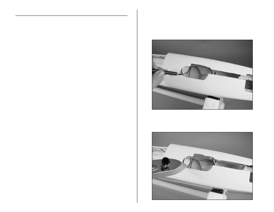
1. Use a hobby knife and #11 blade to trim the covering
to expose the opening for the nose gear retract. Trim the
covering leaving 1/8-inch (3mm) overlap of covering
from the inside edge of the opening so it can be ironed
down to add a clean finish to your model.
2. Use a covering iron to iron the covering inside the
edges of the retract opening.