Maintenance/checkout – Banner RP-RM83F Rope Pull Switches User Manual
Page 6
Wiring
These switch models have redundant pairs of safety contacts, so they may be wired for either single-channel or dual-
channel output to a safety module or E-stop circuit. Monitor contacts may be wired as desired to an external alarm device.
CAUTION: Proper Wiring. Maximum tightening torque of contact screws is specified at 0.8 Nm; do not
over-tighten. Before closing the front cover, verify no wires are trapped. Do not operate the rope pull
without properly closing the cover.
Single-Channel Output: Wire contacts 11/12 together in series to the input of a safety module or E-stop circuit.
Dual-Channel Output: Wire contacts 11/12 independently to the two safety module inputs.
Warning Signal. Switch models RP-RM83F-...E provide a
24 V dc solid-state “warning signal” output, which signals
when the rope tension is either too high or too low, before
the safety contacts open and the switch latches OFF. This
solid-state switch is located inside the wiring chamber next
to the safety output contacts.
–
+
1
2
3
0 V dc
+24 V
1
2
3
Load
Figure 11. Warning Signal Electrical Connections
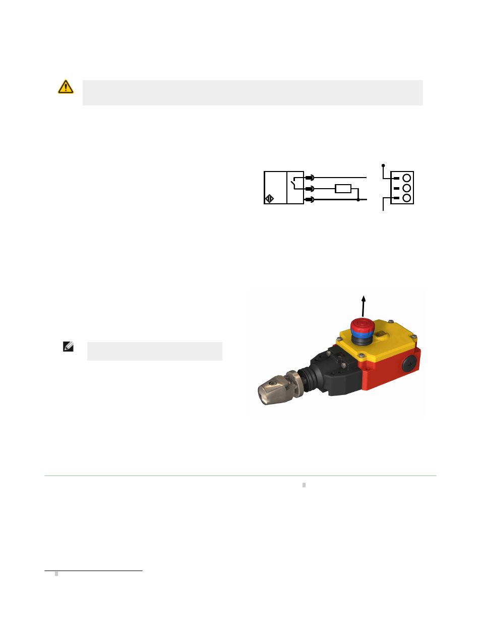
Manual/Latch Reset
E-Stop and Latch Reset. Following the rope pulling/
breaking or the E-stop button being pressed, the latch must
be manually reset. The E-stop can be reset only when
proper tension is indicated. Pull the red E-stop button until
the switch Status indicator changes from Yellow to Green
and the latch makes an audible “click,” indicating that the
latch has been reset.
NOTE: Proper rope tension must be
displayed before the latch can be reset.
Figure 12. Resetting the Latch
Maintenance/Checkout
At switch installation or replacement and at machine set up, a Designated Person
3
must test each switch for proper
machine shutdown response and check the switch(es) and installation for proper operation, physical damage, mounting
(looseness), and excessive environmental contamination. This must also take place on a periodic schedule determined by
the user, based on the severity of the operating environment and the frequency of switch actuations. Adjust, repair, or
replace components as needed. If inspection reveals contamination on the switch, thoroughly clean the switch and
eliminate the cause of the contamination. Replace the switch and/or appropriate components when any parts or
assemblies are damaged, broken, deformed, or badly worn; or if the electrical/mechanical specifications (for the
environment and operating conditions) have been exceeded. Always test the control system for proper functioning under
machine control conditions after performing maintenance, replacing the switch, or replacing any component of the switch.
Additional items that should be included in the checkout and/or regularly scheduled maintenance of a rope pull system:
3 A Designated Person is identified in writing by the employer as being appropriately trained to perform a specified checkout procedure.
RP-RM83F Heavy-Duty Rope Pull Emergency Stop Switches
6
www.bannerengineering.com - tel: 763-544-3164
P/N 141245 Rev. C